Hi, I just wanted to ask a help regarding my project. I need to send data using my ESP32 38 Pins and SIMA7670E GSM Module. I tried AT command testing via PC, and it went well. However, whenever I've tried to test the AT Commands with ESP32, it shows unreadable text.
Here's how I connected their wires:
A7670E VCC TO EXTERNAL 5V 2.4A
A7670E GND TO EXTERNAL GND
ESP32 GND TO COMMON GND (WHERE EXTERNAL GND IS CONNECTED)
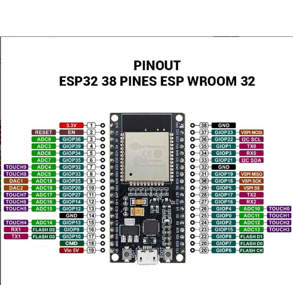
A7670E RXD TO GPIO19 TX
A7670E TXD TO GPIO 18 RX
A7670E PWR_EN TO GPIO4
I TRIED USING A DIFFERENT BAUD RATE, BUT IT WAS STILL UNREADABLE
HERE IS THE CODE I USE TO RUN IN ARDUINO IDE
#include "HardwareSerial.h"

HardwareSerial simSerial(2); // UART2 for GSM

const int PWR_EN = 4; // GPIO4 controls module power

void setup() {
  Serial.begin(115200);
  simSerial.begin(115200, SERIAL_8N1, 19, 18); // RX=19, TX=18
  pinMode(PWR_EN, OUTPUT);

  Serial.println("Starting ESP32 -> A7670E Auto Test...");

  // Power on GSM module
  Serial.println("Powering on A7670E...");
  digitalWrite(PWR_EN, HIGH); // Pulse HIGH to power on
  delay(1000);                // Hold for 1 second
  digitalWrite(PWR_EN, LOW);  // Release
  delay(3000);                // Wait for module to start

  // Test commands
  sendATCommand("AT");
  sendATCommand("AT+CSQ");
  sendATCommand("AT+CREG?");
}

void loop() {
  // Forward A7670E responses to Serial Monitor
  while (simSerial.available()) {
    char c = simSerial.read();
    Serial.write(c);
  }
}

// Helper function to send AT command and display response
void sendATCommand(String cmd) {
  Serial.print("Sending: ");
  Serial.println(cmd);
  simSerial.println(cmd);
  delay(1000); // Wait for response
  while (simSerial.available()) {
    char c = simSerial.read();
    Serial.write(c);
  }
  Serial.println("\n-------------------");
}
I hope someone can help me fix the unreadable text (gibberish text)
try a simple program where you enter AT commands and check for response
e.g. change GPIOs to suit your setup
// ESP32  Serial1 test - for loopback test connect pins RXD1 and TXD1

#define RXD1 16 // can map Serial1 and Serial2 to many ESP32 GPIO pins
#define TXD1 17 // check pin usage https://randomnerdtutorials.com/esp32-pinout-reference-gpios/

// for RS232 shield connect
// ESP32 RXD1 to TTL/RS232 Rx
// ESP32 TXD1 to TTL/RS232 Tx
// connect GND pins together and VCC to 3.3V on ESP32 5V on UNO ect
// for loopback test connect 9-pin D_type connector pins 2 Tx to 3 Rx (pin 5 is GND)

void setup() {
  // initialize both serial ports:
  Serial.begin(115200);
  Serial1.begin(115200, SERIAL_8N1, RXD1, TXD1);
  Serial.printf("\n\nESP32 serial1  test RXD1 pin %d TXD1 pin %d\n", RXD1, TXD1);
  Serial.printf(" loopback test connect pin %d to pin %d\n", RXD1, TXD1);
  Serial.printf("RS232: ESP32 pin %d RXD1 to TTL/RS232 Rx and pin %d TXD1 to TTL/RS232 Tx\n", RXD1, TXD1);
  Serial.printf("RS232 - loopback connect 9-pin D-type pin 2 Tx to pin 3 Rx\n");
}

void loop() {
  // read from Serial1, send to Serial
  if (Serial1.available()) {
    int inByte = Serial1.read();
    Serial.write(inByte);
  }
  // read from Serial, send to Serial1
  if (Serial.available()) {
    int inByte = Serial.read();
    //Serial.write(inByte);     // local echo if required
    Serial1.write(inByte);
  }
}
serial monitor output when AT commands entered
*ATREADY: 1

+CPIN: SIM REMOVED
AT
OK
AT+CGMI
SIMCOM INCORPORATED
OK
AT+CGMR
+CGMR: A131B03A7670M6C
OK
AT+CGMM
A7670E-LASA
OK
AT+CSQ
+CSQ: 16,99
OK
the website presents a lot of nice pictures but no information on connections and how to use the device, e.g. are the Tx and Rx 3.3V logic or 5V logic?
ask the vendor where you purchased the specific SIMA7670 module for a datasheet?
does the serial monitor continuously print garbage or does it stop after a time?
While connected to the PC - can you actually send AT commands to see the baud rate? AT+IPR? might work; otherwise, try to force the baud rate to 115200 with AT+IPR=115200 or enable auto-bauding with AT+IPR=0.