Hello everyone,
I’m working on a VR project and need help getting sensor data from the BNO08x using an ESP32 Dev Board over I²C.
 Hardware I’m Using:
-
BNO08x IMU (GY-BNO080/BNO085 breakout)
 Amazon Link
9DOF AHRS sensor, supports quaternion output and sensor fusion. -
ESP32 WROOM-32 Dev Board by OceanLabz
Amazon Link
Dual-core WiFi + Bluetooth module, USB-C with CP2102 chip.
 Goal:
Goal:
Read accurate Yaw / Pitch / Roll (orientation) data from the BNO08x via I²C using the Adafruit BNO08x library.
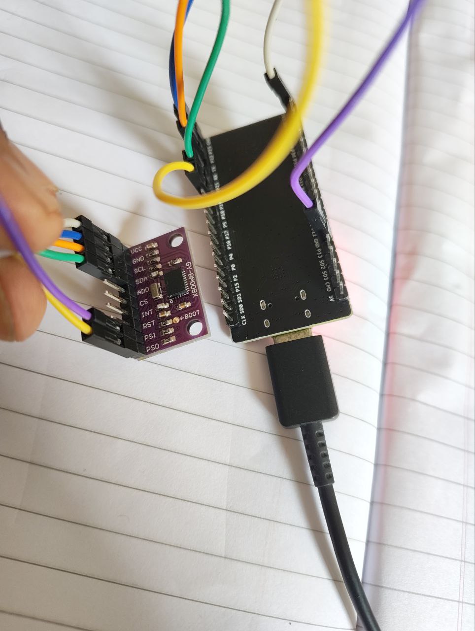
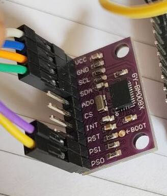
 Wiring Connections (I²C Mode)
| BNO08x Pin | ESP32 Pin | Purpose |
|---|---|---|
| VIN / VCC | 3.3V | |
| GND | GND | |
| SDA | GPIO 21 | |
| SCL | GPIO 22 | |
| PS0 | GND | |
| PS1 | GND | |
| ADO | Not connected | |
| INT | Not connected | |
| RST | Not connected | |
| CS | Not connected |
 Libraries Used
- Adafruit BNO08x Library (installed via Library Manager)
- Wire.h (default I²C library)
- Board: ESP32 Dev Module (from Espressif)
 Step 1: I²C Scanner Test
To confirm the I²C address, I used the standard scanner:
#include <Wire.h>
#define SDA_PIN 21
#define SCL_PIN 22

void setup() {
  Serial.begin(115200);
  Wire.begin(SDA_PIN, SCL_PIN);
  Serial.println("I2C Scanner Running...");

  for (byte addr = 1; addr < 127; addr++) {
    Wire.beginTransmission(addr);
    if (Wire.endTransmission() == 0) {
      Serial.print("I2C device found at 0x");
      Serial.println(addr, HEX);
    }
  }
}
void loop() {}
![]() Output:
Output:
I2C device found at 0x4B
So the sensor is connected properly and acknowledged by the ESP32.
 Step 2: Reading Sensor Data (Code Below)
Then, I tried using the Adafruit BNO08x example for rotation vector output (modified for my pins and I²C address):
#include <Wire.h>
#include <Adafruit_BNO08x.h>

#define SDA_PIN 21
#define SCL_PIN 22

Adafruit_BNO08x bno08x;
sh2_SensorValue_t sensorValue;

struct euler_t { float yaw, pitch, roll; } ypr;
sh2_SensorId_t reportType = SH2_ARVR_STABILIZED_RV;
long reportIntervalUs = 5000;

void setReports() {
  if (!bno08x.enableReport(reportType, reportIntervalUs)) {
    Serial.println("❌ Could not enable report");
  }
}

void quaternionToEuler(float qr, float qi, float qj, float qk, euler_t* ypr) {
  float sqr = qr*qr, sqi = qi*qi, sqj = qj*qj, sqk = qk*qk;
  ypr->yaw = atan2(2*(qi*qj + qk*qr), (sqi - sqj - sqk + sqr)) * RAD_TO_DEG;
  ypr->pitch = asin(-2*(qi*qk - qj*qr) / (sqi + sqj + sqk + sqr)) * RAD_TO_DEG;
  ypr->roll = atan2(2*(qj*qk + qi*qr), (-sqi - sqj + sqk + sqr)) * RAD_TO_DEG;
}

void setup() {
  Serial.begin(115200);
  Wire.begin(SDA_PIN, SCL_PIN);
  Wire.setClock(100000);

  Serial.println("BNO08x I2C Test");
  if (!bno08x.begin_I2C(0x4B, &Wire)) {
    Serial.println("❌ BNO08x not found at 0x4B");
    while (1);
  }

  Serial.println("✅ BNO08x Found!");
  setReports();
}

void loop() {
  if (bno08x.wasReset()) {
    setReports();
  }

  if (bno08x.getSensorEvent(&sensorValue)) {
    if (sensorValue.sensorId == SH2_ARVR_STABILIZED_RV) {
      quaternionToEuler(sensorValue.un.arvrStabilizedRV.real,
                        sensorValue.un.arvrStabilizedRV.i,
                        sensorValue.un.arvrStabilizedRV.j,
                        sensorValue.un.arvrStabilizedRV.k,
                        &ypr);

      Serial.print("Yaw: "); Serial.print(ypr.yaw, 2);
      Serial.print("  Pitch: "); Serial.print(ypr.pitch, 2);
      Serial.print("  Roll: "); Serial.println(ypr.roll, 2);
    }
  }
}
 Output
Despite successful I²C detection at 0x4B, the output is fails with this error:
❌ BNO08x not found at 0x4B
 What I Need Help With
- Is the connection wrong ?
- Is the hardware wrong ?
- Or anything else ?
 Related Posts
I found similar issues by other users like:
Unfortunately, those threads don’t explain how the issue was eventually resolved.
I’ll be uploading photos of my hardware setup shortly in case it helps spot wiring issues.