Yes , i'm using an ESP 32 and i'll give this code a try and i'll get back here
I got this as output:
No response from sensor!
No response from sensor!
No response from sensor!
No response from sensor!
No response from sensor!
No response from sensor!
At this particular point i want to check my connections and verify if my jumper cables are okay
most likely you find some problem there...
You can try swapping the A and B connections, and if that does not work, swap the Tx and Rx connections.
And also check you MAX485 TTL to RS485 modbus.
You can also try this 2400 or 9600 baud rate.
Well i managed to check all the jumper cables and they are all good, I even changed the RS485 module, i tried to switch the A and B connections and tried swap RX2 and TX2 . I'm at a standstill rn and wondering what could be the problem , i was wondering if it could be the Rx and Tx ports i'm using on the ESP 32
You could connect the Rx & Tx pins together with a single jumper wire to form a loopback - no other wires connected. Then a simple sketch that prints a letter/digit/word etc to that port can be used to read back what you have sent to confirm that you have the right pins and the port is working.
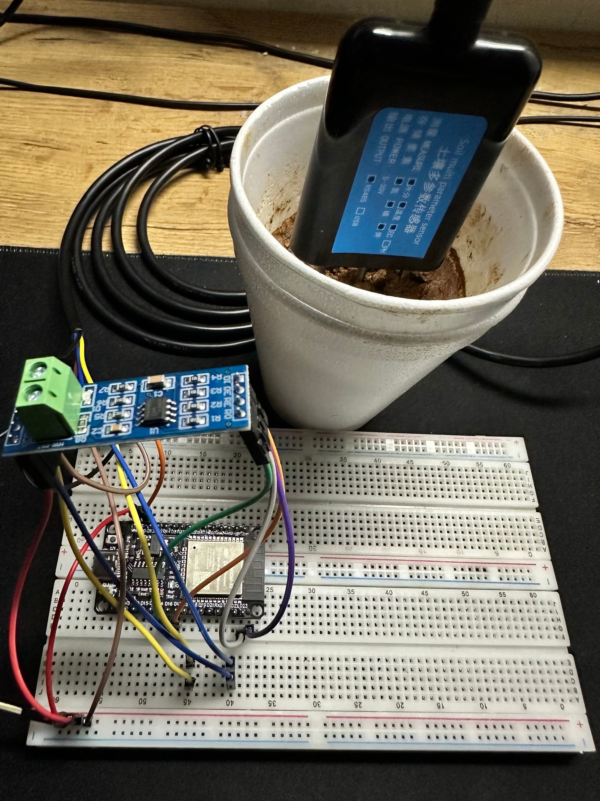
You don't tell what module. I don't see DE/RE wires on your image, but on your code you use them. Neither I see GND.
May I suggest you to open your own fresh topic for your issue.
Post all the components you use, your wiring and actual code.
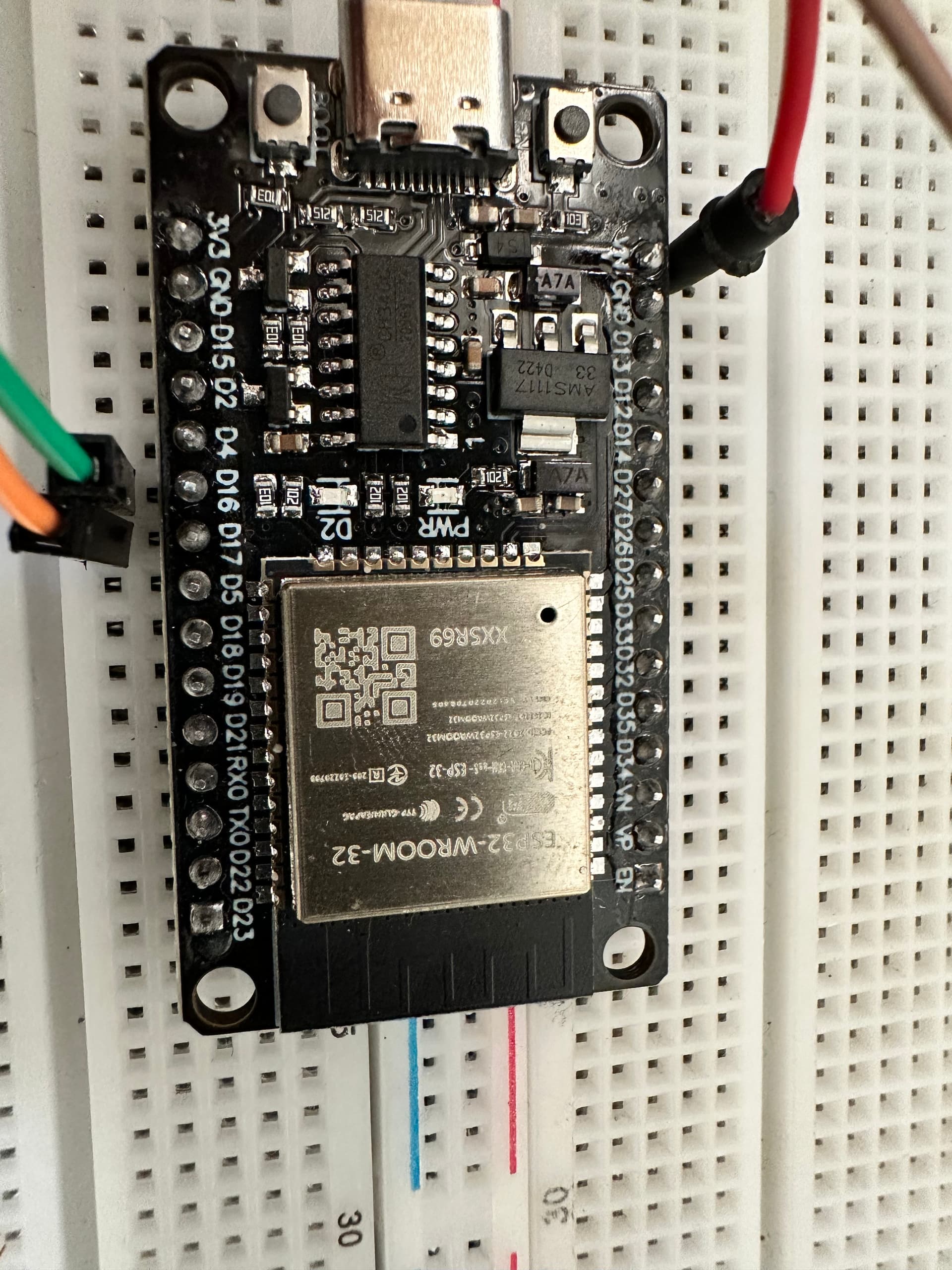
This was just a pic of the type of ESP32 i'm using,but i'm using all the components from the pic provided by Eva-55
Using the Rx and Tx ports on the ESP32?
Could you tell me how you are supplying power? Are you providing power separately to each component, or are you just using a USB cable connected to the laptop?
Since i'm in my dorm room right now i'm currently using the 5V power port and the GRD port from an arduino mega but when i'm at the lab i use a power generator set at 5V
Now it's mega, before it was esp32. Rs485 module should be powered at voltage based on your arduino...
Also, you could power the sensor at little higher voltage. It has range of 5-30V, I wouldn't go with absolute minimum.
I think you misunderstood me a bit , the project is using a ESP 32 as the microcontroller and to power the circuit which includes the sensor i was using the 5V power port from an arduino which i have lying around the room . I will definitely try to power the sensor using more voltage to see if i can get some results.
And the RS485 module at operating voltage of your Esp, 3.3V...
Could you please draft a rough drawing on how everything should be connected
You really should do what I suggested on post #49 to get best support here.
Will do
Hi,
Can I suggest when you are talking readings, you first clean the probes, isopropyl or fresh water and dry them.
Then put them in the soil, take your readings, THEN REMOVE the sensor and clean it.
My reasoning;
The device uses basically electrolysis to do its analysing.
After a while the surrounding soil will be contaminated with the chemical products of that electrolysis.
This may cause erroneous readings.
Using electrolysis and the above method, continuous readings are not possible.
Does that make sense?
Thanks.. Tom.... ![]()
![]()
![]()
![]()