Hello everyone. I'm only implementing the circuit but the led of the wifi module does not turn on.
I have tested with the 3.3v power supply from the arduino uno and with an external power supply connected to the arduino uno. Hardware:
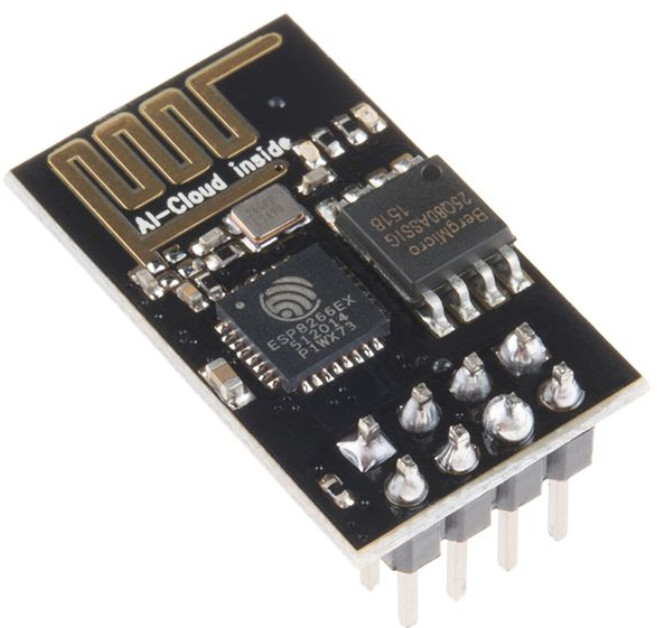
ESP8266 WIFI MODULE ESP01
Arduino Uno Circuit Scheme is like these:
Thank you for the information about your project. However, your description is too general to imagine what mistakes might have been made. Describe how you have connected things like switches. Are they wired to ground? Or +5V? Are there pull-up or pull-down resistors? Post a circuit if there is doubt. In this case, it would be wise to post close up images of your wiring.
Did you use 5V to 3.3V level shifters? Did you provide an adequate 3.3V supply? The Arduino can't supply enough current on the 3.3V pin to properly power an ESP8266.
Thanks for your answer @runaway_pancake . I also tried with 9v charger and it doesn't work.
I have seen tutorials that connect it directly to the arduino to the 3.3v pin and the module's led lights red. What do you recommend me to do?
9V? That's a lot more than 3V ("3VCC").
I wouldn't be surprised if doing that whacked it.
My "suggestion" is a better 3V supply, supposing it's salvageable.
How about two C-cells, maybe two AA's ?
There are 5V adapter modules for the ESP-01, not only have the I/O voltage level translation, but an on board voltage regulator to supply more power to the ESP.
My Uno has plenty of 3.3v juice for that. But if it is not enough to power the ESP, it will be enough to light up the LED for sure.
You should use a voltage divider on the RX pin, to prevent the input voltage exceeding the 3.6v safe limit, or your ESP-01 will probably get damaged at some point. Also you should connect RST to 3.3v VCC as well (not all ESP-01's have a pullup resistor there)
That the red LED doesn't light up, may also be due to it being broken, well not the led itself, but the connection to it. It is placed in the row of four '805' package parts in line with the start of the antenna. First the blue led that is connected to GPIO 1, then 2x current limiting resistors and then the red power LED. Re-melt the solder on either side of the LED and of the resistor right next to it.
It should have done, but the led should still work, the resistor is a 4.7K one, and it is not connected any differently than VCC -> 4.7K -> LED -> GND.
@Deva_Rishi I see. My take-away was that Droid88 might have put the '9V charger' right to the ESP, which I think would suck for it. Maybe it was to the Uno DC-jack (proper polarity?).
Oh man, they have omitted the voltage dividers on the ESP's RX pin. The RX pin on a bare-ESP is not 5v tolerant. The statement made by on of the CEO's has been removed from their website.
A nodeMCU 'may' have a 5v tolerant RX-pin (if it is GPIO 3) But even that is not a certainty.
Someone should write to the moderator to get these projects corrected or removed. But of course that option doesn't exist.
Now look what I've done! (-:
I've never had trouble getting anything Uploaded with a NodeMCU or Wemos. These ESP-01jobs were all that was available at first, but now they're not worth the hassle.