I am struggling to introduce an external power supply for my hardware.
The project I am working on is running on an Arduino Mega. I already have a 12V Power Supply which the Arduino is running on, in addition the 12V is powering a pump and DC Motor and a flow through heater. I then (have a lot of sensors (temperature, flowmeter, HX711) in addition LEDs, Rotary Encoder and an LCD all of which were directly connected to the Power Outlet of the Arduino. I had no issues powering the Arduino and running my software etc. but ran into issues when I ran part of my software which involves pretty much all of the sensors, motors and pump to run at the same time. This however led to issues with the LCD (got funny readings and couldn't display what I wanted to anymore). I did it this way due to lack of electrical understanding. Having put a bit of research in, I probably drew too much current from the Arduino which then caused the issue on the LCD. So far so good. I introduced bypass Capacitors for the Arduino, which didn't solve it. So I ended up buying a 5V PSU.
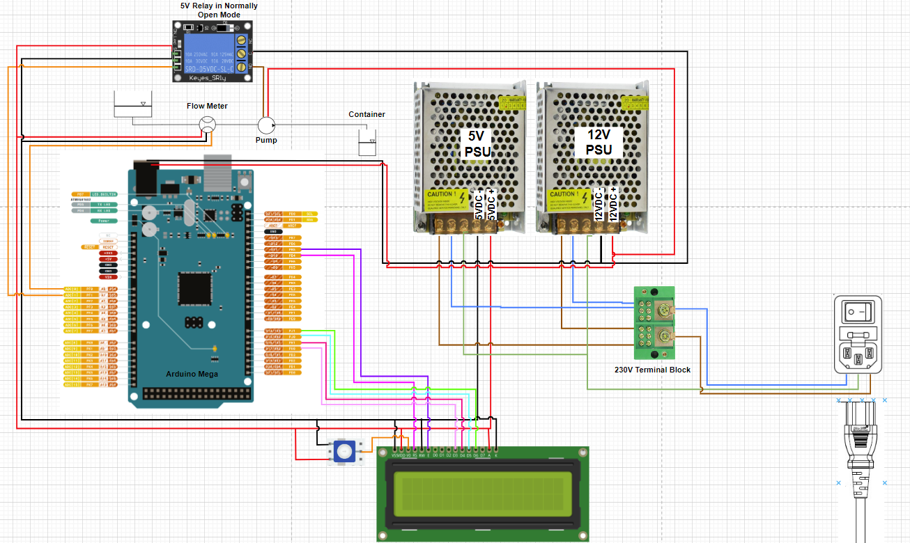
So the current setup looks as followed:
12V PSU --> powers the Arduino, Pump, DC Motor and Flow Through Heater
5V PSU --> I connected all positive and negative outlets of all 5V hardware to this PSU except the LCD, which is still running through the Arduino (I read that there are issues when powering it separate).
Since I have done that, none of my hardware works except the LCD...
I measured the PSUs and I get 5V and 12V on the outlets.
So my question is, is there something that I have to look out for when connecting the hardware to an external PSU but controlling it through an Arduino?
And please excuse that I have not attached an image, I am not by my machine right now.
Questioners know what their hardware and software looks like but the volunteers here do not; you need to fully explain what’s not working, and how it is supposed to work.
Please read all the posting guidelines before asking your questions; follow these guidelines in your post.
Hardware
As always, show us a good schematic of your proposed circuit.
Show us good images of your ‘actual’ wiring.
Give WEB links to your major components.
When you follow the posting guidelines, volunteers can be more effective.
The mains power connectors may well have the earth connected but that does not mean the output grounds are connected. unless you are using isolators you will need to connect the 5 volt ground and 12 volt ground together. It's always been ambiguous how earth, ground, chassis 0volts and commons are connected. Treat earth as a safety feature and grounds as commons so connect grounds (gnd) together. Hope this helps. B.
I have boiled it down to a simpler version now. To show that I am working on. If I get this to work, I will figure the rest out as well.
Please have a look at the connections I am talking about. I think that is what I described in my previous post and I am more than happy to adjust this accordingly.
I am not sure if I fully understand what you mean with "The mains power connectors may well have the earth connected but that does not mean the output grounds are connected."
And as I said in my first post, I am not a trained electrical engineer or electrician, so please forgive if I am not able to grasp it the first time.
I found my mistake, obviously it was one single wire that was connected wrongly...
However I found another issue, that I will be able to resolve by reconnecting.
The HX711 that I am using, are now also connected to the 5V PSU. But the readings are off, by connecting to the Arduino right away, the issue is resolved. Does that have to do with the common ground that was mentioned earlier?
If you look at your diagram the green wire from the mains power connector goes to the earth connections on both switch mode supplies. That is your safety earth or ground. Looking at your power supply negatives (-), they are connected together and to all grounds on your sensors, relays etc. There is no certainty that your negatives and the mains earth are tied together. What can happen in the case of isolated grounds is you can have leakage from you mains supply (be cautious of imported switch mode power supplies) which can be a shock or damage hazard. When you plug your usb cable into your PC the gnd will be earthed via the pc. In a pc the 5v, 3v3 and 12 volt are all referenced against earth, the chassis is connected to earth. I,m sure many out there have seen the spark when pushing in USB connectors where the USB device has it's own supply. So, to be safe connect your ground (-) to the mains earth. This will reference all voltages against earth and improve safety. Hope this explains it. B
I think I understand what you mean.
Still have a few questions though. Not sure if the sketch was not detailed enough, but the negatives of both PSUs are NOT connected (there is a little arch where they cross, sorry for the small picture). I assume you say that as they should be!?
And to the second point, you are saying that I should connect the negative terminals of the PSUs to the earth? Something like this:
Ha, yes I missed the jump over. From experience I had a 5v 5 amp power supply that went rogue. Gave me a shock when working with a nano. Turned out there was around 75 volts to earth though the output was 5 volts. My personal preference in your case would be to connect all grounds together and the mains earth. Look up BigClive on Youtube and see some of the dangerous devices he has dismantled including shocking USB supplies. I spent many years in control and monitoring that set my opinions. A small point I would suggest switching the + v to the pump. That way your pump and most wiring will be at safe ground when the pump is off. Hope that clarifies things. B
You had the Earth (green) wires connected correctly in the diagram before - they should NOT connected to the 0v output of the PSUs. The Earth wires should remain independent from the the rest of the electrical circuits. Disconnect whatever jumper you put between the Earth and black wires!
If you had all this equipment in a metal case, then you would also connect the Earth wire to the metal case. Technically any exposed metal parts that anyone could touch should be Earthed.
The main problem is the 0v output (or Ground as most people call it) should be connected together - the black wires you have labelled as 5vdc- and 12vdc-
They are not a negative, but zero volts -> a "return" or reference for the +5vdc and +12vdc.
They need to be connected together so that other connections between devices are all working from the same reference.
Join them at one central location like the power supply connectors, or at the Arduino power input barrel.
Do not run a mesh of 0v wires from device to device, or there will be ground loops.
For example the LCD and the Arduino are powered from separate supplies, and without their ground wires connected the LCD sees the incoming data from the Arduino as a floating/unknown /crazy voltages that mean nothing.
Keep you devices connected in more of a star configuration, with the 0v/grounds connected together centrally at the PSUs.
Excuse the rough low quality drawing
Do not run the wires around from device to device in a daisy chain if it can be avoided
That actually resolved most of my issues! I connected the 12V, 5V, and Ardunio GND together and then connected it to the "earth" which solves 99% of the problems.
I have however one very very odd issue that I have not faced before. I am using a the following flow meter, which until today never made any problems. But the rewiring must have messed things up and I don't understand why. (https://www.amazon.com/DeLonghi-5213214671-Delonghi-Flowmeter/dp/B00IJZD2VC)
The data wire is connected to 18TX1 on my Arduino mega, the negative end to GND and the positive to 5V. This used to be perfectly fine. Now I don't get any readings.
However if I short the + and - of the flowmeter it works.... I get the right desired liquid amount every single time. I am clueless of what is going on.
I am trying the following code:
#include <FlowSensor.h>
const int Pump = 10;
int actual_volume =0;
int desired_volume = 100;

FlowSensor Sensor(YFS201, 18);
unsigned long timebefore = 0;  // same type as millis()

void count() {
  Sensor.count();
}
void setup() {
  Serial.begin(115200);
  Sensor.begin(count);
  //Pump
  pinMode(Pump, OUTPUT);
}

void loop() {
  for (actual_volume; actual_volume < desired_volume;) {
    digitalWrite(Pump, HIGH);
    Sensor.read();
    actual_volume = Sensor.getVolume() * 1000;
    Serial.print(actual_volume);
    Serial.print("ml --- ");
    Serial.print(millis());
    Serial.println("ms");
  }
  digitalWrite(Pump, LOW);
}
when connected to + and GND, no reading, when + and - shorted it works....
I am trying everything here...
If connecting to 12V instead of 5V I get one pulse every time I switch the 12V PSU on (Its important to note, that it used to work on 5V). However if on, nothing happens until I restart, which again, gives me one pulse (or an equivalent of 1ml the way I calibrated the flowmeter)
It's important that the chassis Earth wire is NOT connected to the black 0v wires (or "ground" as we call it). It's the green wire in your diagram, and coming from the mains IEC socket -
Although it can work, it means a mains fault current could affect the regulated voltage side of the PSUs, or the reverse. And it's likely there can be some amount of hum and noise on that earth wire too.
If the PSU chassis had a floating voltage on it, like 75 volts, then there is a fault either with the PSU or the earth wiring that should be fixed.
Does that flow meter connect to an analog pin? I would connected it to digital pin 2 like in the flowsensor example, since you dont have a lot of pins used.
Probably use
FlowSensor Sensor(YFS201, 2);
and adjust the wiring to suit.
EDIT: I see you said 18tx1 and in the diagram it looked like it was connected to A0. Either way I would change to digital pin 2 anyway.
Try connecting a 0v from the flow sensor to the Arduino 0v
Thanks again for your help!
It turns out the Flow Sensor was broken. I tried everything incl. replacing the Arduino, cables etc. The last remaining item was the Flow Sensor, which now works after replacing it.
Actually I now have another problem that I can't seem to fix. I have a reboot when I start part of my software. I thought that would have been fixed with the two different PSUs (reason why I implemented them in the first place). But now I still have the same issue. I don't have the weird reading on the LCD anymore but random reboots and sometimes the Arduino turns into a stage where the "L" LED on the Arduino flashes continuously, so do the LCD and an external LED (to show the machine is powered on). I can only get out of this mode by switching the power off and on again, sometimes it directly goes into this weird behavior other times it takes some time. The flashing seems to be getting quicker and quicker.