Good evening to everyone,
I am struggling with this issue: I followed all the found posts related to sine waves reading with Arduino Nano.
The signal is taken from a signal generator HP 33120A and has a frequency of 1kHz.
I tried to remove the delay as I read, but anyway you can see the code below, even though it is very very simple:
void setup() {
  // initialize serial communication at 9600 baud rate:
  Serial.begin(9600);
}

// the loop routine runs over and over again forever:
void loop() {
  // read the input on analog pin 0:
  float sensorValue = analogRead(A0);
  // print out the value you read:
  Serial.println(sensorValue);
  //delayMicroseconds(100);
}
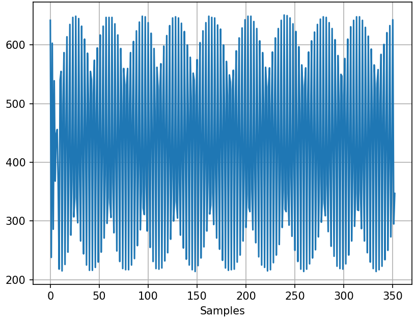
What I get from python is attached here.
Can anyone help me?
Thank you in advance!
In your reading, did you notice that a "sine wave" is AC? Meaning that half of wave is positive and the other half is negative? That is what "sine" means.
You must be very careful to not connect an AC signal to the Arduino pin unless it is properly processed by external circuitry.
What you're seeing is aliasing. There's no way you can get ~4-byte samples at 2kHz over a 9600 baud serial link.
You should significantly increase the baud rate, and you might want to configure the ADC in free-running mode, or trigger it from a timer, so you get a more accurate sampling rate.
The delay is completely insignificant, compared to the time it takes (1 millisecond) to print a single character at 9600 Baud.
Collect data, then print.
void loop() {
 int data[200]; //room for 200 values
  // read the input on analog pin 0:
  for (int i=0; i<200; i++) data[i] = analogRead(A0);
  // print out the values:
  for (int i=0; i<200; i++)  Serial.println(data[i]);
}
The default data collection rate on the Arduino Uno is about 10,000 samples per second, so 200 samples is a small fraction of one cycle of a 1 kHz signal. You can reintroduce the delay to lower the sample rate (minimum sample rate is twice the highest frequency in the signal).
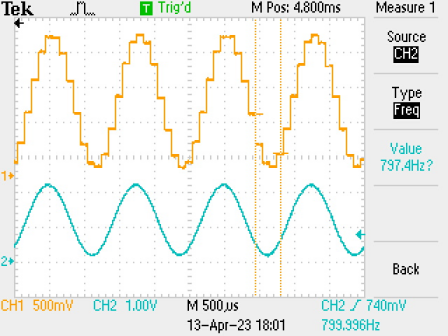
if you are sampling a 1KHz sine wave at 10000samples/second it should look something like (running on an ESP32)
blue trace is the original sine wave (about 750Hz which was offset to give a positive voltage) and the yellow trace is the resultant samples output by a DAC
Not true I’m afraid , it relates to the mathematical definition , it does go positive and negative , but that is not what “sine” in this context means , it is short for sinusoidal, different from sign