I am working on QVGA 2.2 tft spi 240*320 display.I completed all basic steps and connections.My connection of display with arduino uno as describe bellow.
Port 11 = MOSI
Port 12 = MISO
Port 13 = SCK
Port 10 = CS
Port 8 = Reset
3.3V = LED
GND=GND
3.3=Vcc
I connect my LCD with arduino uno using above pin connection.If any modification or suggestion in this connection required then please let me inform.
I am also getting confused about library. Currently I'm using TFT library,GFX library and ili9341 library for interface LCD with my arduino board.Suggest me other library if it's equire to be included in my program. Send me link for that if possible.
I want to inform you that there is no error shown by compiler so i think that there must be something wrong in connection.I get nothing on display except full white screen.I want to know the reason behind it. Please help me to get out from this.
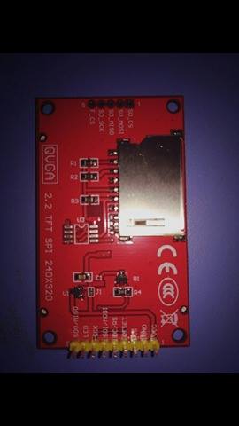
Ah-ha. You have the display with "yellow header" and unmounted Flash chip. (unmounted 5-pin SD/Flash header)
I possess one of those. I get a White Screen too. I am sure that I had it working at some stage.
I can read the registers. Everything seems normal for a genuine ILI9341V controller chip. i.e. identical results to the more common display with "black header" and unmounted 4-pin SD header.
Yes, I use 3.3V logic.
I have no idea what is "wrong" with my yellow-header ILI9341. If the Reset values of all the registers are identical to the black-header displays, I would expect identical behaviour from identical software.
The yellow-header display has been on the Ebay market for some time.
I would guess that it has many happy owners. Even some who have mounted a Flash chip.
I don't know about display with black header. I have display with yellow header. Can you please tell me that why i am not able to get any output on my display.I tried a lot with using different libraries though i am not able to run even basic program of LCD i.e. can't see anything on display.Is there any problem regarding connection or anything else?
Port 11 = MOSI
Port 12 = MISO
Port 13 = SCK
Port 10 = CS
Port 8 = Reset
Port 9=DC
3.3V = LED
GND=GND
3.3=Vcc
When I don't understand what's happening, I start using measuring equipment, e.g. a scope.
I once had a resistor marked 2.2k, but it actually was 8.2k, and my OVR7670 camera got no clock.
The key with these displays when using a 5V Arduino board is to use level converters as described in step 2 here.
Try an Adafruit_ILI9341 library example such as graphicstest and make sure you configure the pins in the sketch correctly and add the RESET line too (not in the sketch example as provided), with your setup you would use:
Hmm the reset pin need to define and attach.
The example code of graphic test is working fine.
But as I remove the usb port after loading the code in arduino, the display become blank and as again connect the usb to laptop its working fine.
I didnt get why this happen.
Any comment plz.
My yellow header display has always used 3.3V GPIO. Both with Arduino and with ARM controllers.
And yes, I always control RESET pin.
Apart from the Flash chip footprint, the only difference between the Black and Yellow header modules is that the LED pin controls the backlight via transistor Q1 and 1k0 resistor R4.
I get identical results from my readreg diagnosis sketch. Likewise, I can read registers and ID via Library methods. I have NEVER stressed the controller with 5V logic.