I am new to the Arduino world and this is my first project attempt.
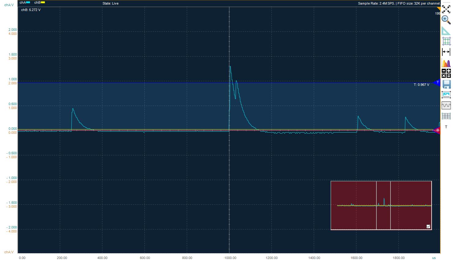
I am working on a project to count radiation pulses. These pulses are of different energies / pulse heights and can come in very quickly (as quick as 10 usec between pulses). I believe I need to use the on board ADC to do this or use an external ADC. See attached screen shot of what the pulses look like. A quick rising edge and then a longer trailing edge.
I have a MKR 1310 board.
I began testing with a signal generator and using the and all works good. But I believe this is only applicable if the pulses cross the TTL threshold of 2 volts. My pulses can be anywhere from 100 mV to 3.3 V.
I tried to use the ADC analogRead function and a basic count flag and if statement for current_count > previous_count to catch the rising edge, but this appeared to be far too slow after further research. I read that this only samples at about 485 usec which would only allow me to count 2000 PPS and it didn't even do this. About 60 was its maximum when feeding in a sine wave.
I read up and downloaded a fast counter code using DMA to store the values and I am told this can sample as fast as 2 usec (which would be great). The code displaying the time to fill the 1024 buffer does display about 2048 usec and I can selectively print out the sampled values from anywhere in the buffer.
Here is my problem now. I need to check all of these values to see if it is a pulse. I don't think I can do this before the buffer fills and overwrites the data I want to check.
In my checking routine launched when the buffer is full, I am again looking for the rising edge, then checking if a lower threshold was crossed before incrementing a counter (and I am sure this takes longer than the 2 usec samples that are filling and overwriting this buffer). It doesn't matter what frequency I put in a sine wave at, I get 1 to 2 counts per second when it should be 100, 1000, 20000, etc.
I am hoping the experienced people on this forum might be able to direct me to a simple solution. The simplest for me would have been the ability to put in an upper and lower threshold on the digital interrupt pulse counter but I don't think that is possible.
I have no clue as to your electronics experience but start here: searching for "window comparator circuit" then goto: Design of Window Comparator Circuit w/ Mutually Exclusive LED Indicators - Electrical Engineering Stack Exchange. These will not solve your problem but they will get you to the point where you can. With this approach you can set your levels etc. Many of the circuits use 741 op-amps, instead use a single rail one that is fast enough or better yet use a comparator however you will probably have to use a pull up with them.
Good Luck & Have Fun!
Gil
At 10 µs no chance for an OpAmp to work. Get a comparator.
The 100 mV - 3.3V is a problem. You have to make sure the noise level in your signal is well below 100 mV or you will get spurious readings.
After shoring up your signal you probably need interrupts indeed to capture them.
gilshultz:
Many of the circuits use 741 op-amps,
That's just historical and basically means "just about any run-of-the-mill OpAmp that you happen to have in your parts box will do just fine here". By modern standards it's a really crappy OpAmp.
As wvmarle says, you need an analog comparator. Fortunately the SAMD21 microcontroller on the MKR1310 has two dual analog comparators built-in.
The following code sets up the SAMD21's positive analog comparator input on analog pin A4. The negative input is connected to an internal resistive voltage scaler set at around 103mV. The comparator output is sent to digital pin D10, but also generates an event on the event system. (The event system is a 12 channel peripheral-to-peripheral highway, that allows communication between them without the need for CPU intervention). The 32-bit TC4 (and TC5) timer is set to count these incoming events and displays the number of detected pulses in the console window every second:
// Count pulses between 100mV and 3.3V on analog pin A4, comparator output on D10, 100kHz test PWM on D7
void setup() {
  // Serial port (console) ///////////////////////////////////////////////////////////////////

  SerialUSB.begin(115200);                  // Open serial communications on the native USB port
  while (!SerialUSB);                       // Wait for the console to open

  // Power management ///////////////////////////////////////////////////////////////////////

  PM->APBCMASK.reg |= PM_APBCMASK_EVSYS;        // Activate the event system peripheral
  PM->APBCMASK.reg |= PM_APBCMASK_AC;           // Activate the analog comparator peripheral

  // Generic clock ///////////////////////////////////////////////////////////////////////////

  GCLK->CLKCTRL.reg = GCLK_CLKCTRL_CLKEN |         // Route the 32.768kHz GCLK1 to the Analog Comparator analog clock
                      GCLK_CLKCTRL_GEN_GCLK1 |
                      GCLK_CLKCTRL_ID_AC_ANA;
  while (GCLK->STATUS.bit.SYNCBUSY);               // Wait for synchronization

  GCLK->CLKCTRL.reg = GCLK_CLKCTRL_CLKEN |         // Route the 48MHz GCLK0 to the Analog Comparator digital clock
                      GCLK_CLKCTRL_GEN_GCLK0 |
                      GCLK_CLKCTRL_ID_AC_DIG;
  while (GCLK->STATUS.bit.SYNCBUSY);               // Wait for synchronization

  GCLK->CLKCTRL.reg = GCLK_CLKCTRL_CLKEN |         // Route the 48MHz GCLK0 to timers TC4 and TC5
                      GCLK_CLKCTRL_GEN_GCLK0 |
                      GCLK_CLKCTRL_ID_TC4_TC5;
  while (GCLK->STATUS.bit.SYNCBUSY);               // Wait for synchronization

  // Configure port pins /////////////////////////////////////////////////////////////////////

  // Enable the port multiplexer for the Analog Comparator channel 1 input AIN[1] on analog pin A4
  PORT->Group[g_APinDescription[A4].ulPort].PINCFG[g_APinDescription[A4].ulPin].bit.PMUXEN = 1;

  // Connect the AIN[1] input to A4 - port pins are paired odd PMUXO and even PMUXE
  // B specifies the AC channel 1 input: AIN[1]
  PORT->Group[g_APinDescription[A4].ulPort].PMUX[g_APinDescription[A4].ulPin >> 1].reg |= PORT_PMUX_PMUXO_B;

  // Enable the port multiplexer for the Analog Comparator channel 1 output on digital pin D10
  PORT->Group[g_APinDescription[10].ulPort].PINCFG[g_APinDescription[10].ulPin].bit.PMUXEN = 1;

  // Connect the AC/CMP[0] output to D10 - port pins are paired odd PMUXO and even PMUXE
  // H specifies the AC channel 1 output: AC/CMP[1]
  PORT->Group[g_APinDescription[10].ulPort].PMUX[g_APinDescription[10].ulPin >> 1].reg |= PORT_PMUX_PMUXO_H;

  // Event system ////////////////////////////////////////////////////////////////////////////

  EVSYS->USER.reg = EVSYS_USER_CHANNEL(1) |                                // Attach the event user (receiver) to channel 0 (n + 1)
                    EVSYS_USER_USER(EVSYS_ID_USER_TC4_EVU);                // Set the event user (receiver) as timer TC4

  EVSYS->CHANNEL.reg = EVSYS_CHANNEL_EDGSEL_NO_EVT_OUTPUT |                // No event edge detection
                       EVSYS_CHANNEL_PATH_ASYNCHRONOUS |                   // Set event path as asynchronous
                       EVSYS_CHANNEL_EVGEN(EVSYS_ID_GEN_AC_COMP_1) |       // Set event generator (sender) as analog comparator channel 1
                       EVSYS_CHANNEL_CHANNEL(0);                           // Attach the generator (sender) to channel 0

  AC->EVCTRL.reg = AC_EVCTRL_COMPEO1;                     // Output event upon AC compare on channel 1

  TC4->COUNT32.EVCTRL.reg = TC_EVCTRL_TCEI |              // Enable asynchronous input events on the TC4 timer
                            TC_EVCTRL_EVACT_COUNT;        // Configure TC4 to COUNT upon receiving an event

  // TC4 Timer ///////////////////////////////////////////////////////////////////////////////

  TC4->COUNT32.CTRLA.reg = TC_CTRLA_WAVEGEN_NFRQ |          // Set-up TC4 in Normal Frequency (NFRQ) mode
                           TC_CTRLA_MODE_COUNT32;           // Configure TC4/TC5 timers for 32-bit mode

  TC4->COUNT32.CTRLA.bit.ENABLE = 1;          // Enable timer TC4
  while (TC4->COUNT32.STATUS.bit.SYNCBUSY);   // Wait for synchronization

  TC4->COUNT32.READREQ.reg = TC_READREQ_RCONT |                               // Enable a continuous read request
                             TC_READREQ_ADDR(TC_COUNT32_COUNT_OFFSET);        // Offset of the 32-bit COUNT register
  while (TC4->COUNT32.STATUS.bit.SYNCBUSY);                                   // Wait for synchronization

  // Analog Comparator ///////////////////////////////////////////////////////////////////////

  AC->COMPCTRL[1].reg = AC_COMPCTRL_HYST |            // Enable input hysteresis
                        AC_COMPCTRL_OUT_ASYNC |       // Enable comparator output in asynchronous mode
                        AC_COMPCTRL_MUXPOS_PIN1 |     // Set the positive input multiplexer to pin 1
                        AC_COMPCTRL_MUXNEG_VSCALE |   // Set the negative input multiplexer to the voltage scaler
                        AC_COMPCTRL_SPEED_HIGH;       // Place the comparator into high speed mode
  while (AC->STATUSB.bit.SYNCBUSY);                   // Wait for synchronization

  AC->SCALER[1].reg = AC_SCALER_VALUE(1);  // Set the negative input voltage scale to 103mV
                                           // Vscale = Vdd * (VALUE + 1) / 64 = 3.3V * (1 + 1) / 64 = 103mV

  AC->CTRLA.bit.ENABLE = 1;                // Enable the analog comparator peripheral
  while (AC->STATUSB.bit.SYNCBUSY);        // Wait for synchronization

  AC->COMPCTRL[1].bit.ENABLE = 1;          // Enable the analog comparator channel 1
  while (AC->STATUSB.bit.SYNCBUSY);        // Wait for synchronization

  // TCC0 Timer 100kHz PWM Test Output on D7 ////////////////////////////////////////////////////

  // Feed GCLK0 to TCC0 and TCC1
  GCLK->CLKCTRL.reg = GCLK_CLKCTRL_CLKEN |         // Enable GCLK0 as a clock source
                      GCLK_CLKCTRL_GEN_GCLK0 |     // Select GCLK0
                      GCLK_CLKCTRL_ID_TCC0_TCC1;   // Feed GCLK0 to TCC0 and TCC1
  while (GCLK->STATUS.bit.SYNCBUSY);               // Wait for synchronization

  // Enable the port multiplexer for pin D7
  PORT->Group[g_APinDescription[7].ulPort].PINCFG[g_APinDescription[7].ulPin].bit.PMUXEN = 1;

  // D7 is on ODD port pin PA21, TCC0/WO[7], channel 3 on peripheral F
  PORT->Group[g_APinDescription[7].ulPort].PMUX[g_APinDescription[7].ulPin >> 1].reg |= PORT_PMUX_PMUXO_F;

  // Normal (single slope) PWM operation: timer countinuouslys count up to PER register value and then is reset to 0
  TCC0->WAVE.reg |= TCC_WAVE_WAVEGEN_NPWM;         // Setup single slope PWM on TCC1
  while (TCC0->SYNCBUSY.bit.WAVE);                 // Wait for synchronization

  TCC0->PER.reg = 479;                            // Set the frequency of the PWM on TCC0 to 30kHz: 48MHz / (479 + 1) = 100kHz
  while (TCC0->SYNCBUSY.bit.PER);                  // Wait for synchronization

  // The CCx register value corresponds to the pulsewidth in microseconds (us)
  TCC0->CC[3].reg = 240;                          // TCC0 CC1 - 50% duty cycle on D7
  while (TCC0->SYNCBUSY.bit.CC3);                 // Wait for synchronization

  TCC0->CTRLA.bit.ENABLE = 1;                     // Enable the TCC0 counter
  while (TCC0->SYNCBUSY.bit.ENABLE);              // Wait for synchronization
}

void loop() {
  SerialUSB.println(TC4->COUNT32.COUNT.reg);      // Output the number of detected pulses from TC4's COUNT register
  delay(1000);                                    // Wait for 1 second
}
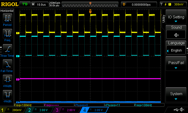
To test this code, I got the microcontroller to produce a 100kHz, PWM square wave on D7, passed this through a 10k/1k resistive divider on my breadboard to generate a 300mV signal, then plugged the divider's output into A4. My oscilloscope shows the 300mV, 100kHz square wave input on A4 (yellow) and the reconstituted 3.3V, 100kHz square wave comparator output on D10 (light blue):
Meanwhile the TC4 timer is keeping a count of the number of pulses received.
Thanks for the comments so far. My 'real' electronics experience is 20 years old and I did work with 741s back then! I thought I may have to use a hardware / software solution for this so I will evaluate what you all suggest.
MartinL - I will look at this code later today. Thank you very much for the actual code - I have some pieced together coding experience but trying to learn what the hardware is capable of and how to manipulate it in new code is a lot.
I will update as I move along and figure things out. Really appreciated folks.