I noticed in some other posts, the problem was the way the circuit was created for the system, so I'm wondering if that is the case for my circuit as well? I tried to copy the diagrams in the link as much as I possibly could, but feel free to tell me if something is off with the way I've connected everything together. I'm also using the exact same code that they've posted in the link.
So it looks like when I remove the sensor from the A0 pin, the reading appears to be a bit more reasonable (something greater than 0), but the value still doesn't quite change when I put it into different environments. It's when I put it back into the A0 pin that the value goes back to 5.
I checked the power supply, and it did say that it outputs 5V.
Here is the code as well
 Arduino Watering Plant Kit

 A setup that allows for remote/local control of a pump, as well as reading sensors.

 Built using the Arduino IoT Cloud service

 Components used:
- Arduino Nano 33 IoT
- Arduino Nano Screw terminal Adapter
- 5V submersible pump.
- 1 meter watering pipe.
- USB wall adapter
- Water container.
- Micro-USB cable.
- Open ended USB Cable.
- Soil moisture sensor.
- Grove LED button
- 3D-printed enclosure (optional)
- Short Grove cable (20cm)
- Long Grove cable (50cm)
- Long 3-pronged Grove cable (50cm)
*/

/* ------------- START CONFIG ------------- */
constexpr int BUTTON_PIN = 4;
constexpr int LED_PIN    = 5;
constexpr int RELAY_PIN  = 6;
constexpr int MOIST_PIN  = A0;


int raw_moisture = 0;
/* ------------- END CONFIG ------------- */

#include "thingProperties.h"
#include <Bounce2.h>

Bounce b;
unsigned long startedWatering;

void setup() {
  Serial.begin(9600);
  delay(1500);

  b.attach(BUTTON_PIN,INPUT_PULLUP);
  b.interval(25);
  pinMode(LED_PIN, OUTPUT);
  pinMode(RELAY_PIN, OUTPUT);

  // Make sure the pump is not running
  stopWatering();

  // Connect to Arduino IoT Cloud
  initProperties();
  ArduinoCloud.begin(ArduinoIoTPreferredConnection);
  setDebugMessageLevel(4);
  ArduinoCloud.printDebugInfo();

  // Blink LED to confirm we're up and running
  for (int i = 0; i<=4; i++) {
    digitalWrite(LED_PIN, HIGH);
    delay(200);
    digitalWrite(LED_PIN, LOW);
    delay(200);
  }

}

void loop() {
  ArduinoCloud.update();

  // Read the sensor and convert its value to a percentage
  // (0% = dry; 100% = wet)
  raw_moisture = analogRead(MOIST_PIN);
  moisture = map(raw_moisture, 793, 382, 0, 100);
  Serial.println(moisture);

  // Set the LED behavior according to the moisture percentage or watering status
  if (watering) {
    digitalWrite(LED_PIN, HIGH);
  } else if (moisture > 40) {
    // good, LED is turned off
    digitalWrite(LED_PIN, LOW);
  } else if (moisture > 10) {
    // warning, slow blink
    digitalWrite(LED_PIN, (millis()%1000)<500);
  } else {
    // need water, fast blink
    digitalWrite(LED_PIN, (millis()%500)<250);
  }

  // Stop watering after the configured duration
  if (watering && (millis() - startedWatering) >= waterTime*1000) {
    stopWatering();
  }

  // Read button status
  b.update();
  if (b.changed() && b.read() == false) { // button pressed
    if (watering) {
      stopWatering();
    } else {
      startWatering();
    }
  }
}

// This function is triggered whenever the server sends a change event,
// which means that someone changed a value remotely and we need to do
// something.
void onWateringChange() {
  if (watering) {
    startWatering();
  } else {
    stopWatering();
  }
}


void startWatering () {
  watering = true;
  startedWatering = millis();
  digitalWrite(RELAY_PIN, HIGH);
}

void stopWatering () {
  watering = false;
  digitalWrite(RELAY_PIN, LOW);
}

void onWaterTimeChange()  {
  // Add your code here to act upon WaterTime change
}
type or paste code here
I got a chance to add some more flux to the carrier shield, and it looks a bit better now, although I'm still getting the same value (-55) after this and a re-upload of the code to the board, so I'm not too sure where to go from here
Yes. The pads and pins need to be fluxed and heated first. After half a second, touch the solder to the pad/pin/iron junction. Just as the solder begins to flow (is melted and wicks onto the pad/pin surface), remove the solder then remove the iron. Total time, one second per pin.
I think I figured out another part of the problem; I accidentally soldered the pins a spot further than they were supposed to be, so they weren't quite aligned correctly on the board. I've been having some trouble desoldering the pins to re-align them, so I ended up buying another board with some header pins pre-installed. Hoping that could solve the issue
To de-solder multiple pins, "tack" a heavy gauge COPPER wire to the pins, load with flux, then "fill" the copper wire and pins with solder. The copper wire will transfer the heat along its length. Add tension to the part being removed (be careful not to melt plastic or pull/push too hard). Keep running the iron across the copper wire until all pins are released.
Another way to remove "header" pins is to cut the plastic between the pins and remove each pin separately.
Wanted to provide a quick update: I got the new board with the pins and connected it to the screw terminal adapter, updated the code so that the mapping could be a bit more accurate. and tested out the pump with the 5V power supply on its own. I was able to get moisture readings that made a bit more sense thankfully, and I was able to confirm that the power supply is able to turn the pump on, so I think we're making some more headway. I'll likely end up using the other board to practice some soldering and de-soldering techniques later, but definitely appreciate you providing some guidance on how I could potentially get the pins off the board. I'll likely use this video for reference later on.
Now I'm just running into an issue where the pump won't power on even when the moisture level readings are low, and I'm not able to see the moisture reading on the dashboard on Arduino cloud.
Sounds like everything is "working" on their own, so now just to find the missing puzzle piece.
Pump not powering on... Is the pump power going through a relay? Does the relay energize? How is the relay getting power? Does the relay share a ground with the Arduino? Does the pump share ground with the other devices? Do you ever hear the pump turn on? Does the pump produce the force needed to raise water 1m in the pipe?
Please, make a pencil/paper wiring drawing/diagram of all your connections, that must be legible.
So the pump power is going through a relay, but it looks like the relay isn't turning on for some reason. It does share a ground with the Arduino, and the pump is also grounded to the Arduino. I don't hear the pump turn on, but perhaps that's because the relay isn't turning on.
I've attached a diagram of what the tutorial page provides; I've got my system connected the exact same way
You must label your devices... but I will guess at some of them...
These things should not be connected:
The diagram shows VIN connected to 5V. VIN is for 7.5vdc to 12vdc.
The diagram shows 3v3 connected to the relay VCC... relays are probably 5V, not 3v3.
Is the LED on pin 5 really 3v3?
Will your Bounce code recognize 3v3 as "HIGH"?
Some more good news: I realized part of the reason why the relay was never turning on was because the way the code was written before, it never actually turned on the relay to power the pump until a trigger from the dashboard prompted it to, so it wouldn't actually trigger when the moisture value changed. I edited the code a bit more so that once the moisture value reached a certain threshold, the relay would turn on, and the pump would start working. Thankfully, I was able to get the relay working, and the pump works as well, so I think the problem should be fixed!
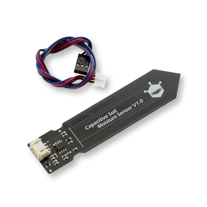
I recommend a capacitive soil moisture sensor, the type you have in the picture will erode. Capacitive sensor doesn't come in direct contact with the soil, that's the trick.