Hello everyone,
I read so many different tutorials related to Nema 17,
In first place I started to use the motor driver l298n though its not ideal choice is my understanding when I read so much about this motor (Nema 17).
Currently I am using:
Nema 17 Stepper Motor, bipolar, 42 N-cm,
1.5 A, 42 x 42 x 39 mm,
4 wires with 1 m cable and connector
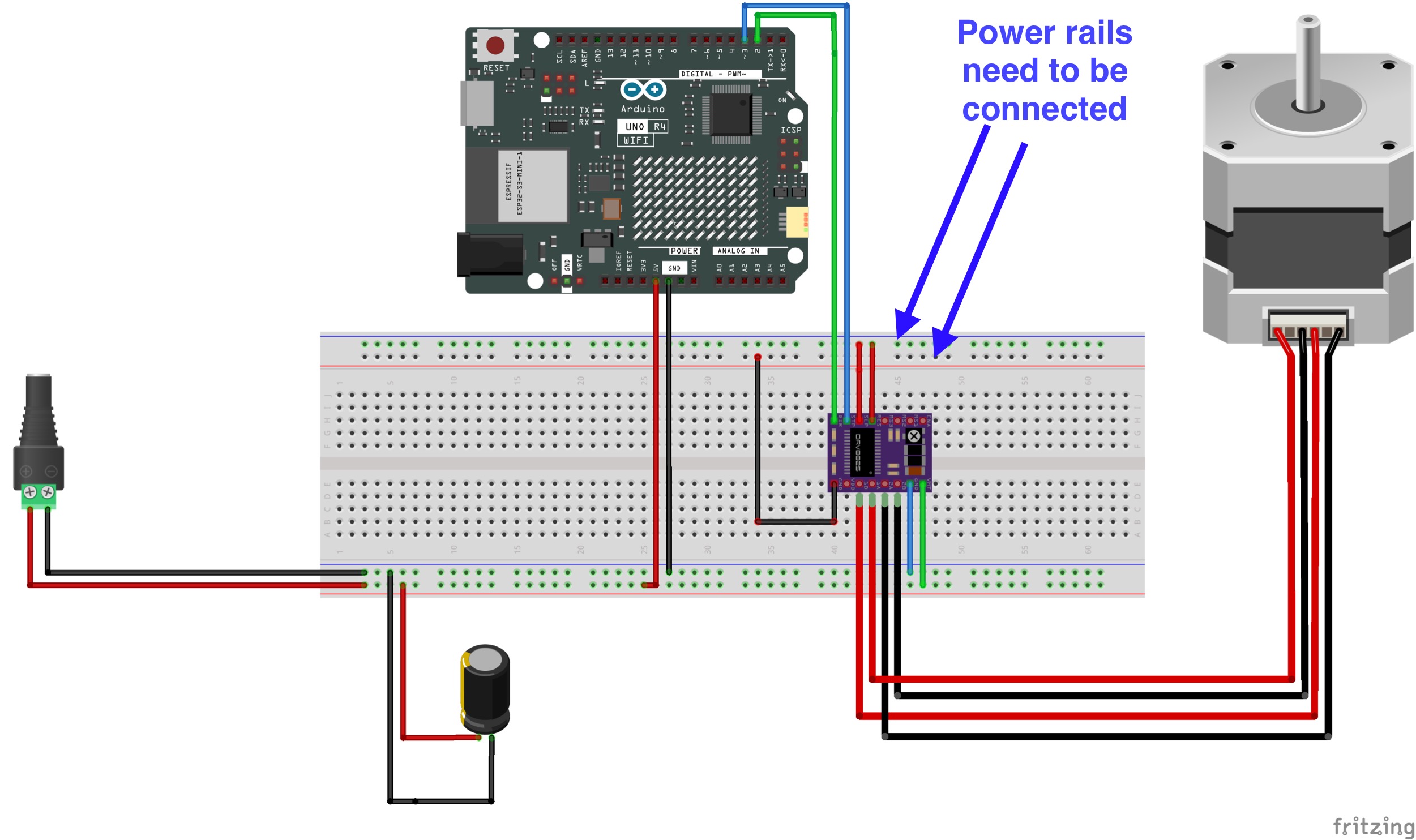
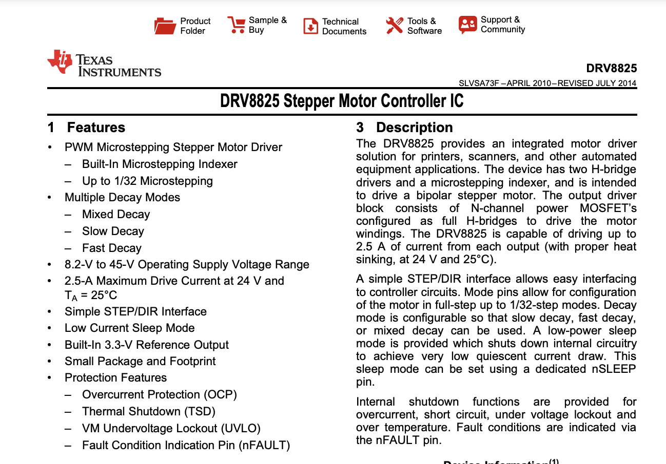
So I have been using drv8825
this is how I made the wiring diagram and I have set the potential meter to 0.5v
when I measured with voltmeter.
I have read so much what a good value of volt to set in order to not make the motor overheat (the sink).
This is how I made the wiring part:

On the diagram I am using a 100uf capacitor.
the sink is very cold all the time so I am glad with that compare to when I was using the other motor-driver.
it works really well but honestly I am really new to this kind of things when it comes to make more complex stuff related to voltage.
Below is an example sketch I have used based on following tutorial:
makerguides drv8825 motor driver with nema 17
/* Example sketch to control a stepper motor with
   A4988/DRV8825 stepper motor driver and
   Arduino without a library.
   More info: https://www.makerguides.com */

// Define stepper motor connections and steps per revolution:
#define dirPin 2
#define stepPin 3
#define stepsPerRevolution 200

void setup() {
  // Declare pins as output:
  pinMode(stepPin, OUTPUT);
  pinMode(dirPin, OUTPUT);
}

void loop() {
  // Set the spinning direction clockwise:
  digitalWrite(dirPin, HIGH);

  // Spin the stepper motor 1 revolution slowly:
  for (int i = 0; i < stepsPerRevolution; i++) {
    // These four lines result in 1 step:
    digitalWrite(stepPin, HIGH);
    delayMicroseconds(2000);
    digitalWrite(stepPin, LOW);
    delayMicroseconds(2000);
  }

  delay(1000);

  // Set the spinning direction counterclockwise:
  digitalWrite(dirPin, LOW);

  // Spin the stepper motor 1 revolution quickly:
  for (int i = 0; i < stepsPerRevolution; i++) {
    // These four lines result in 1 step:
    digitalWrite(stepPin, HIGH);
    delayMicroseconds(1000);
    digitalWrite(stepPin, LOW);
    delayMicroseconds(1000);
  }

  delay(1000);

  // Set the spinning direction clockwise:
  digitalWrite(dirPin, HIGH);

  // Spin the stepper motor 5 revolutions fast:
  for (int i = 0; i < 5 * stepsPerRevolution; i++) {
    // These four lines result in 1 step:
    digitalWrite(stepPin, HIGH);
    delayMicroseconds(500);
    digitalWrite(stepPin, LOW);
    delayMicroseconds(500);
  }

  delay(1000);

  // Set the spinning direction counterclockwise:
  digitalWrite(dirPin, LOW);

  //Spin the stepper motor 5 revolutions fast:
  for (int i = 0; i < 5 * stepsPerRevolution; i++) {
    // These four lines result in 1 step:
    digitalWrite(stepPin, HIGH);
    delayMicroseconds(500);
    digitalWrite(stepPin, LOW);
    delayMicroseconds(500);
  }

  delay(1000);
}
though I have changed the pins just if you look at the wire-diagram
Is this a good way of do the wiring?
Notice The code is just an example.
My plan further on it's to have a schedule that triggers the motor every 8 hours.
this will be for a cat-feeder I am building
also I will conntrol everything from a web-server is my plan that I am injecting with openVPN.
Do you see any problem with the way I am doing this?
Please give me like feedback of how I could improve the stuff.
One thing I was thinking of would a better thing to use a 200uf and then turn up the potential meter to 0.75V?
Would I gain like more power or such?