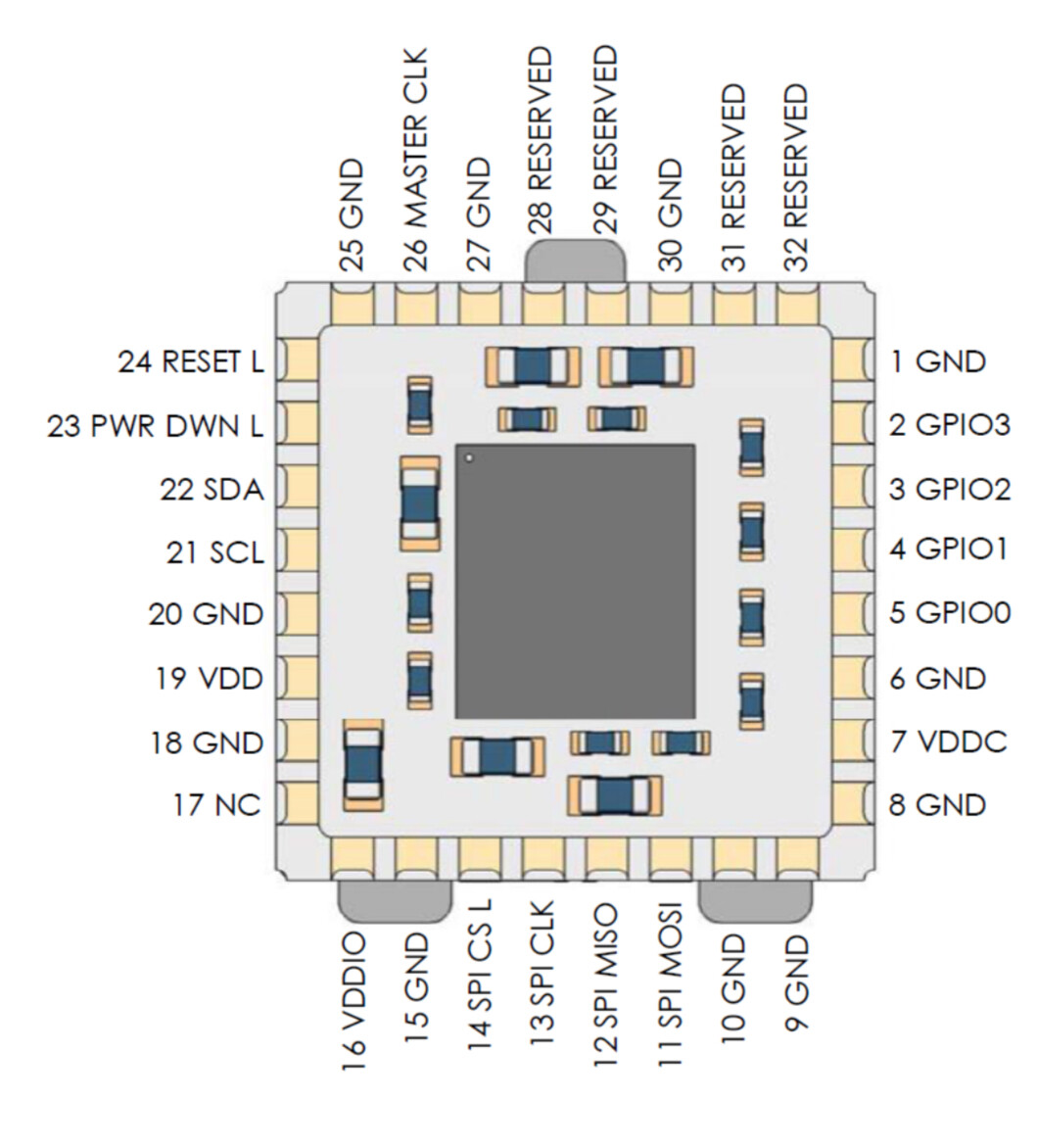
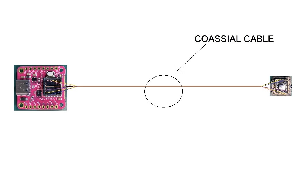
Hi everyone, I'm new to the forum, and as a start I would like to offer you this very interesting project! I need to create an extension for my Lepton flir camera, I have the Lepton 3.5 thermal imager, a 1700mm cable with 7 ultra thin coaxial cables, and a motherboard with USB type-C output where the Lepton is housed. I have to remove the motherboard housing block and from there by soldering the cables I should get to the Lepton camera and solder all the coaxial cables behind the thermal imager, the problem is that from the pin out of the thermal imager there are many pins, I would like to know from you which ones they are essential to make it work, Thanks in advance
Caricamento: IMG_9861.jpeg…


Someone smarter than I will have to tell you about that cable, but I'd start by looking for a schematic of the breakout board.
What does the other end of the cable look like? The board looks like you can (must?) use serial, I2C and SPI.
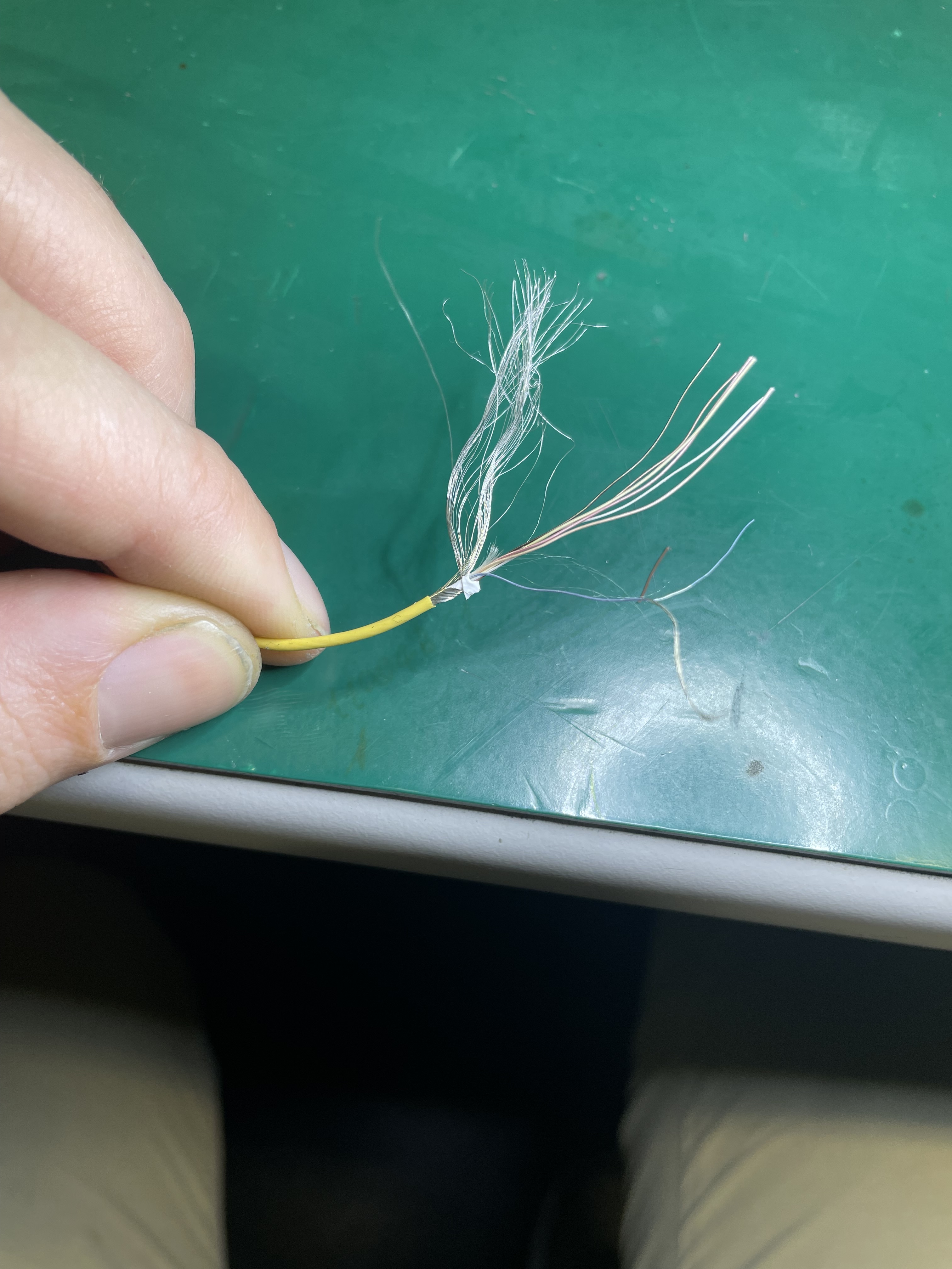


This is the motherboard without the block of connection of the Lepton. Unfortunately, to take it off two paths of GPIO went off. But I think that they are not useful for my purpose. Basically, I need to connect a part of the cable to the motherboard pins and the other part of the cable to the pins of Lepton, the soldering will be done under a microscope.
Thanks xfpd for the reply, I'm interested in knowing which pin to connect via the cable I showed you to make it work, do you think that with 7 coaxial wires you can make it work?this camera has a shutter which is used to calibrate the image every now and then, I tell you this because I imagine that this type of movement is performed by a GPIO, maybe I'm wrong🤷🏼
The board seems to be ready for serial (tx, rx), spi (mosi, miso, clk, cs) and i2c (sda, scl, v+, gnd)... and USB. What is your code using?
I can't understand, don't use the code, the card's output is USB type-C which is recognized as any video device (such as a webcam)
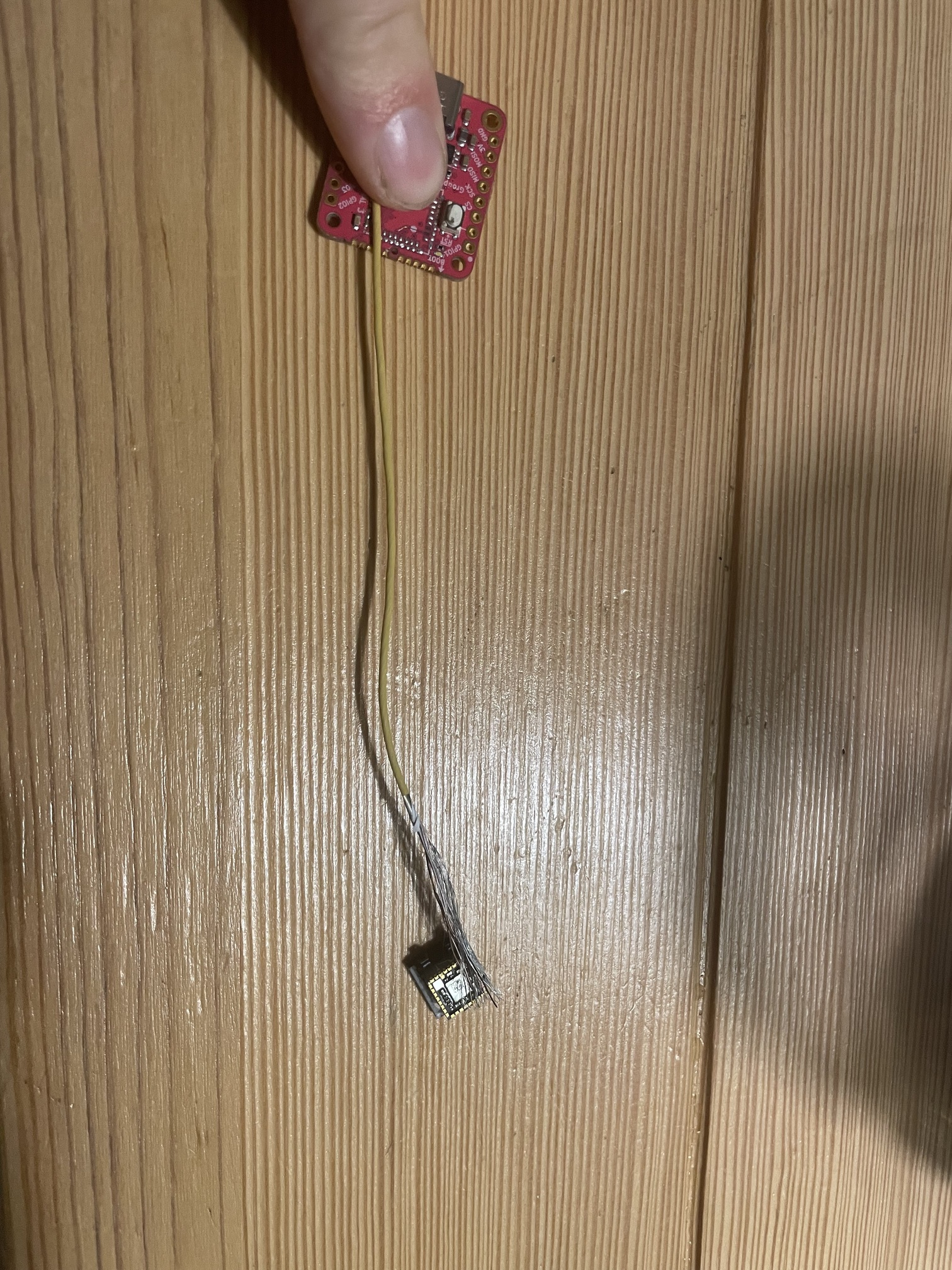
That is not how it goes together. The sensor (the square thing you removed) goes into the receiver (the square thing on the red board). Use programming to retrieve the images from the board.


I don't think that to work I have to connect every single pin, I know it's difficult to understand which pins to connect to make it work correctly, I could connect them all using two cables or three but I would like to avoid doing this cumbersome thing
Repair the pad and trace, replace the sensor in socket, and use the board as originally intended.
This topic was automatically closed 180 days after the last reply. New replies are no longer allowed.