Greetings from Wonderful Wyoming. As a newbie I'm hoping a few Obi Wan Arduino types might weigh in on my first-ever Nano project.
It gets pretty cold up here, so if the temperature gets below say, 25º F, I want my Generac generator to start automatically, run for a few minutes, then shut off for an hour or so (the generator is factory set to start if wires GENST1 and GENST2 are connected).
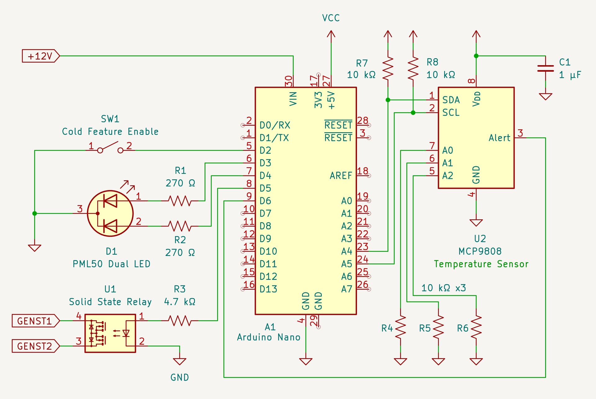
The idea is to use a Nano with a single switch input to enable the cold weather feature. A dual LED will indicate system status (feature enabled, enabling recommended, error(s), etc). A MCP9808 Temp Sensor IC reports temperature to the Nano via I2C.
Any thoughts on this schematic would be much appreciated - from layout to functionality or otherwise. But go easy on me, folks - it's my first time using both KiCAD and Arduino!
sounds like you short the GENST1 and GENST2 connections - any idea what voltage may be on these connections?
possibly a relay would be a solution
make sure you build hysteresis into the on/off control algorithm otherwise it may be switching continuously
You did good, it is hard to believe this is your first attempt. The only thing I would change is R7 and R8 to 4.7K but with it on one PCB it should work OK as you have it.
Thanks for the prompt and thoughtful replies. I should have mentioned a few things that may or may not affect the design:
• Generac describes GENST1 and GENST2 as "dry contacts." Apparently, simply touching these two wires together will cause the generator to start, and the generator stops when they are disconnected.
• This PCB will be enclosed in a junction box (i.e. out of the weather) but it will be outdoors. I'm hoping the Arduino's temperature rating of "-40°C to 85°C" is sufficient for most conditions I'd encounter up here in the Cowboy State.
• The MCP9808 sensor has a programmable temperature alert output pin which I may or may not use. The data sheet describes this as an open-drain output that requires a pull-up resistor. Is it safe to assume I could use the Arduino's internal D6 pull-up - or would it need an external pull-up as with SDA and SDL?
• Finally, I'm planning to source about 19 mA each to those two LEDs on D3 & D4. Hopefully that will be enough for bright indicator lights. Any experiences in that regard would be welcome.
Before you go any further on assumptions, PLEASE confirm your assumptions about the two wires! Does the generator start and run and generate power while the two wires are connected? And does the generator stop only when the wires are disconnected?
What happens when the generator does not start when the wires are connected? Too cold, no fuel, other errors?
Best to include some monitoring of the actual AC output as long as you are in the design stage.
The Arduino website shows an Operating Temperature Range of "-40°C to 85°C" although they also list a "Recommended Temperature Range" of "-25°C to +70°C."
Yes, but you need to know the voltage that's across them and be sure what you are using to switch them is capable of handling that voltage.
'Dry' means that the contacts you use are not connected to anything else, which you have achieved in your design. Typically a switch or relay contact not used for anything else is considered to be dry.
Yes, this is important. I haven't tried it in the field yet, but the Generac controller has other starting protocols that must be met before it sends voltage to the starter motor (e.g. a master enable switch, front panel switch on AUTO, etc).
My understanding is that if all other conditions are met, shorting the GENST1 and GENST2 wires will send a start signal to the generator and disconnecting them sends a stop signal.
But good to verify all this before committing to a PCB. Sound wisdom!
OK, thank you. I will verify the voltage when I get back to the generator unit.
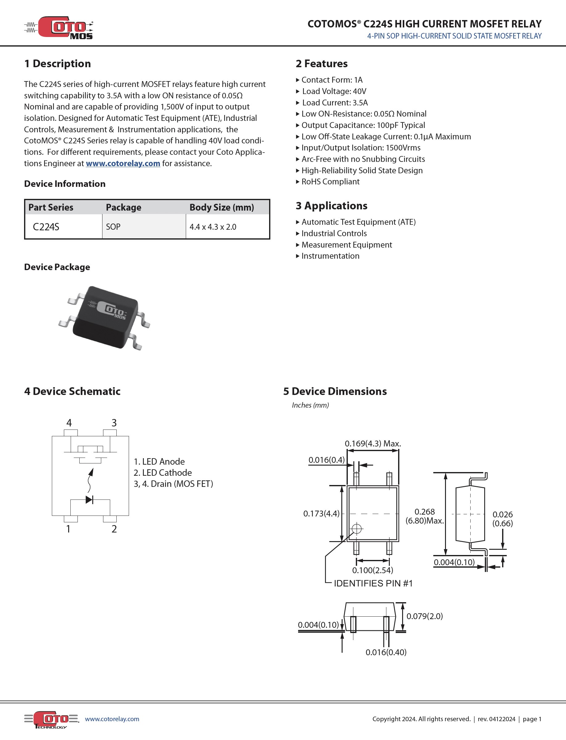
So would it be safe to say the C224S Solid State Relay is OK to use as long as the GENST1 and GENST2 voltage is below the relay's 40VDC Load Voltage? Spec sheet attached:
I would get the entire project working before committing to a PCB. Then for most one-offs, skip the PCB as much fun as they can be.
And at the end of that hour, if the temperature is below 25º F run again for a few minutes?
That neatly sidesteps the hysteresis issue. The reason to turn on is T below 25º F, the reason to turn off is time (a few minutes). By the time you care about the temperature again (an hour or so) it's rinse and repeat time.
This could be a very simple program we'd all love to see done non-simply.
Have you considered the ways this can fail and the implications? The Generac probably acn't be killed, but you don't want to risk telling it to be on all the time if something gets stuck in the logic or for wahtever reason.
Yes, I'd like to use an ordinary +5v relay, but the little buggers typically take around 70 mA in current draw for the coil. I understand Arduino pins don't like to sink/source much more than 20 mA. That's what makes the Solid State Relay so attractive - only 1 mA - which is easily supplied by Pin D5.
I highly recommend you determine if the two leads are actually switching DC or is it AC. That will have a difference on a solid state relay. The safest until you know for sure is to use a mechanical relay module. You can check with the manufacturer to be sure.
Thanks, Dave. This is a good idea and a relay would be my first choice. Check out this slick new unit from Adafruit.
My challenge here, which I should have mentioned earlier, is I'm limited to 100 mA. This allows me to use the +12VDC output from my control box without having to build a separate power supply. Two LEDs at 20 mA each, a 50 mA relay coil, and the Ardunio current is pushing that 100 mA limit. This is why the Solid State Relay (SSR) seems so attractive.
As others have suggested, I can prototype the circuit and try it in the field once I determine the GENST1 and GENST2 voltages and if they're compatible with this SSR.