Any feedback on if my schematics is ok for this project would be very appricated. I'm relatively KiCad and this is the first time working with 3v3 devices (Nano IoT 33), so not sure if I'm doing this is the best way.
Quick summary of what I'm doing is the following
I currently have something similar running off a regular Nano but I wanted to use a Nano IoT33 to use it with MQQT platform.
*The device is used to control a solenoid that when open allows water to flow, measured by the flow meter.
*SW_Push is a float switch that will pause the system for 10 minutes to prevent overflow.
*Rotary encoder is to control menu's and control device.
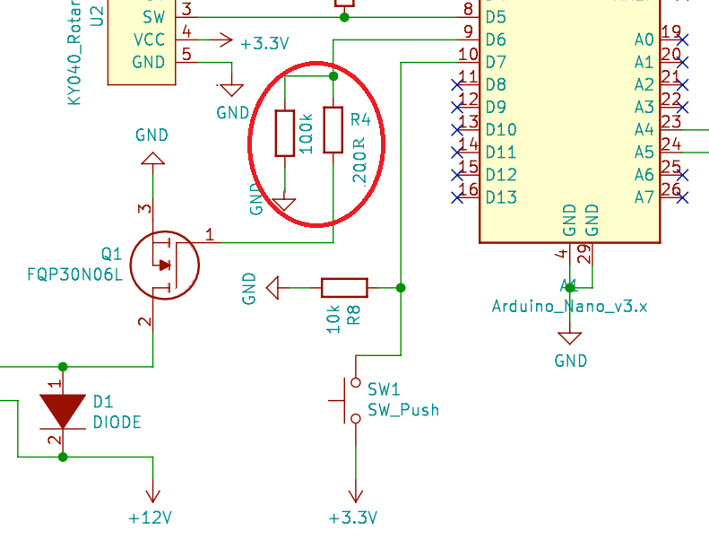
Not sure If I've set the NPN flow meter right (https://www.aliexpress.com/item/32414902642.html?spm=a2g0o.9042311.0.0.7e9d4c4dfXEsWn). I've tried to do a pull-up resistor with a voltage divider to step down to 3.3v, but it confused me and looks weird as GND and 5V only have a couple of resistors between them, which seems wrong and too close to a short. Any advice here would be great.
*I also used a LLC for SLA and SDA on the LCD2004. I'm not sure if that is overkill and if I can just use a voltage divider instead but struggled to confirm this online.
*On my current prototype I have working on a regular Nano the solenoid can occasionally crash the Arduino. I was unsure if I needed more than a fly back diode to protect the microcontroller.
*Any other ideas/feedback would be greatly appreciated.
R1,2,3 probably not needed. The rotary encoder module probably has pull-ups on board, which is why it has a Vcc pin. Alternatively, leave Vcc unconnected and use INPUT_PULLUP on D3,4,5.
Connect float switch between D7 and ground, set INPUT_PULLUP on D7. If long cable to switch, add 1K~4K7 pull-up to 3.3V also. Do not take 3.3V to switch, due to risks of short-circuit.
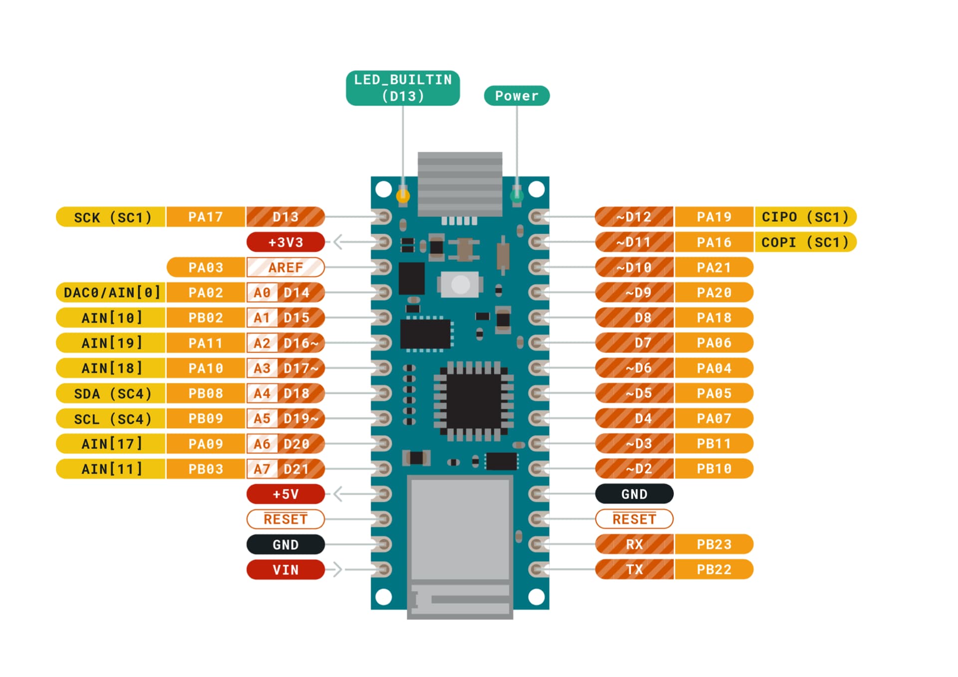
Schematic shows Nano V3, not Nano33. Can same pinout be used? For example are A3, A4 SDA & SCL on Nano33?
RV1 is connected to Vcc of 20x4 display. This is definitely incorrect. Please post link to the specs of the display.
Level converters may not be required on SCL/SDA lines, depending on the display. Connecting 5V & ground to the display but leaving SCL/SDA unconnected, measure the voltages on SCL/SDA pins of the display with multimeter. If voltages are 5V, level converters are needed. If voltages are zero, connect SCL/SDA to Nano without level converters and test with an example sketch. 3K3 or 4K7 pull-ups to 3.3V may be required on SCL/SDA lines. Voltage dividers cannot be used on SCL/SDA lines because they are bi-directional.
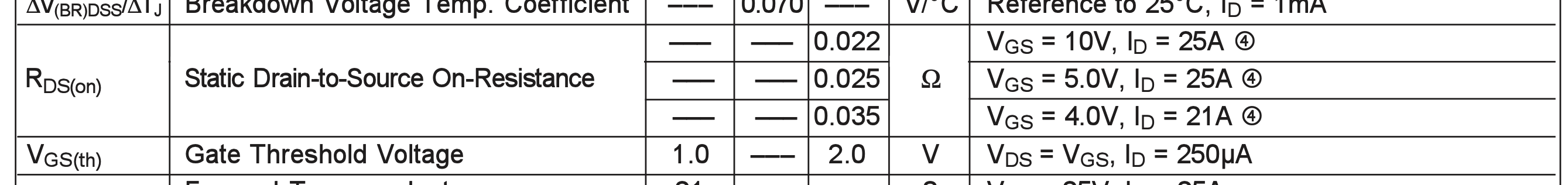
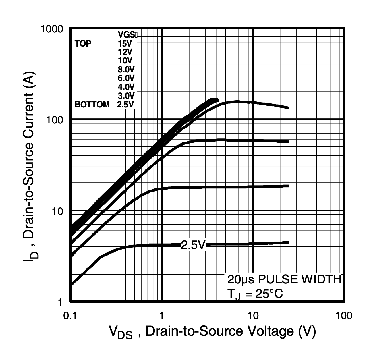
With only 3.3V on it's gate, the MOSFET may not achieve as low an Rds-on as it does with 5V on the gate. Depending on current required by solenoid and length of time solenoid is engaged, MOSFET may overheat.
Hi
The MOSFET Gate has a very small current, but the 200R resistor serves to limit the Arduino pin current in case the MOSFET fails and the Gate short circuits to GND, and is not too large to affect impedance.
The 100K resistor (10K recommended by other users) serves to act as a pulldown to ensure the MOSFET remains off while the Arduino starts up.
Great, that makes it easier. I had been getting a lot of wobble with the encoder and on my breadboard this configuration worked the best, but I will try yours on a breadboard next week.
How long is a long cable? On the current layout its about 50cm long.
The file was pulled from the official website and it states the layout is the same. Image below.
The solenoid will typically be on continuously for anywhere from 10 min to 2 hours at a time, with 10 mins breaks in between as the float switch triggers.
Thanks for all the great info. It's given me a lot to think about and test next week.
So the internal pull-ups should be fine. But will the wires be longer in the final installation?
You checked it, that's great. It's a different chip on Nano33 compared to Nano V3 and sometimes the exact same pinout cannot be achieved.
You connect the wiper of a pot to the Vcc pin of an LCD? That is definitely not a good idea and will cause all kinds of problems. Are you sure that's what you did?
The gate threshold voltage is the voltage at which the MOSFET just begins to conduct. You really need another 1~1.5V over that to switch the MOSFET on harder to get a low resistance between source & drain. With 5V on the gate, no problem, but woth only 3.3V you have less than 1V above the threshold. It might be ok, but keep an eye, or rather a finger, on the MOSFET during testing. If you can't keep your finger on it, attach a heatsink.
Hi,
I appreciate that this is one of you first attempts at a CAD circuit diagram.
You have done well in keeping it uncluttered and well labeled.
Just to make it easier to read and more towards a standard approach, the S1 and Q1 circuits could be layed out so the gnd icons pointed down and the voltage icons pointed up.
This way you will see current always flowing top to bottom in most cases.
What I mean is, I was getting multiple signals from one rotation. For example, one rotation CW would show up in SerialMonitor as CW,CW,CW,CCW. and the number would be +3 from 1 turn (ie +1+1+1-1). This wasn't consistent, and I would often get between -1 to +4 from any turn.
I don't think it would get any longer than 1m but it will most likely be only 20-30cm on the final prototype.
The potentiometer is only 0-100ohms and is usually set to between 20-35ohms. This was reduces the brightness of the LED display. I originally had a fixed resistor, but I wanted to be able to control it more so when with this. I saw a ton of people recommending this on forums when i implemented it 2 years ago. What issues do you think it could cause?
There were a ton of MOSFETS I looked into but I saw this one recommended a few times and in my research I saw people saying it would be ok as the solenoid is only 12V 1.5A when the MOSFET is rated at 60V 32A, so it should be fine, but I will test the temperature.
I have some TO220 heatsinks spare, so i can always throw them on if it is. Would you know of any MOSFETS that would be better than the choice I've made?
Sounds like crucial signal edges from the encoder are getting missed. This is likely to be a code problem that extra pull-up resistors won't help with. Are you using a library? Which one? Are you using interrupts?
It will reduce the operating voltage of the logic chips on the LCD, as well as reducing the backlight. This could make the LCD unreliable and vulnerable to phantom powering though the SCL/SDA pins, which can be damaging. Why won't you post a link to the details of this display?
I know they exist, but can't remember any model numbers. The other problem with them is that they all seem to be surface mount. I have never seen a thru-hole part with a significantly lower gate threshold voltage than the one you are using. This is a problem, in my opinion, because I'm not good at soldering smd components and you need breakout boards in order to use them for prototyping on breadboard.
I actually assumed it was my coding but I got it half working and moved on about 6 months ago with the intention of having another go when I had more time whilst moving other projects forward. I'll have a go again shortly when I get this on a breadboard
I found the schematic for the dfrobot i2c adaptor board. Unfortunately I can't see an easy way to dim the backlight. The most common i2c adaptor boards like this one have an extra 2-pin jumper which can be used to disable or dim the backlight, but your adaptor (assuming it really is this model) does not.
The only option I can think of would be to attach a fine wire to the P3 pin of the pcf8574 chip and connect that to a PWM pin on the Arduino.
Thanks for the info. I'll just remove the potentiometer. That is probably the reason I've had the occasional screen turn into nonsense flickering and random characters. Very rare but it happened once or twice.
Yes, worth trying. I suspect either will be ok, but, as I said monitor the temp when in use. Would be interesting to know how these two models compare in this situation. If you can measure the current flowing though them and the voltage drop across them that would be useful.