I wanted to control a solenoid (the M) using the 3.7V battery but with this configuration I get a voltage drop of about 2 volts between D and S even if the load is not connected.
Using an external battery the circuit works and I don't have any voltage drop. I don't understand why using the same battery to power up the esp and the solenoid this isn't working out the same.
EDIT: I found the problem and it was the wiring of post #13:I plugged the load to source instead of drain.
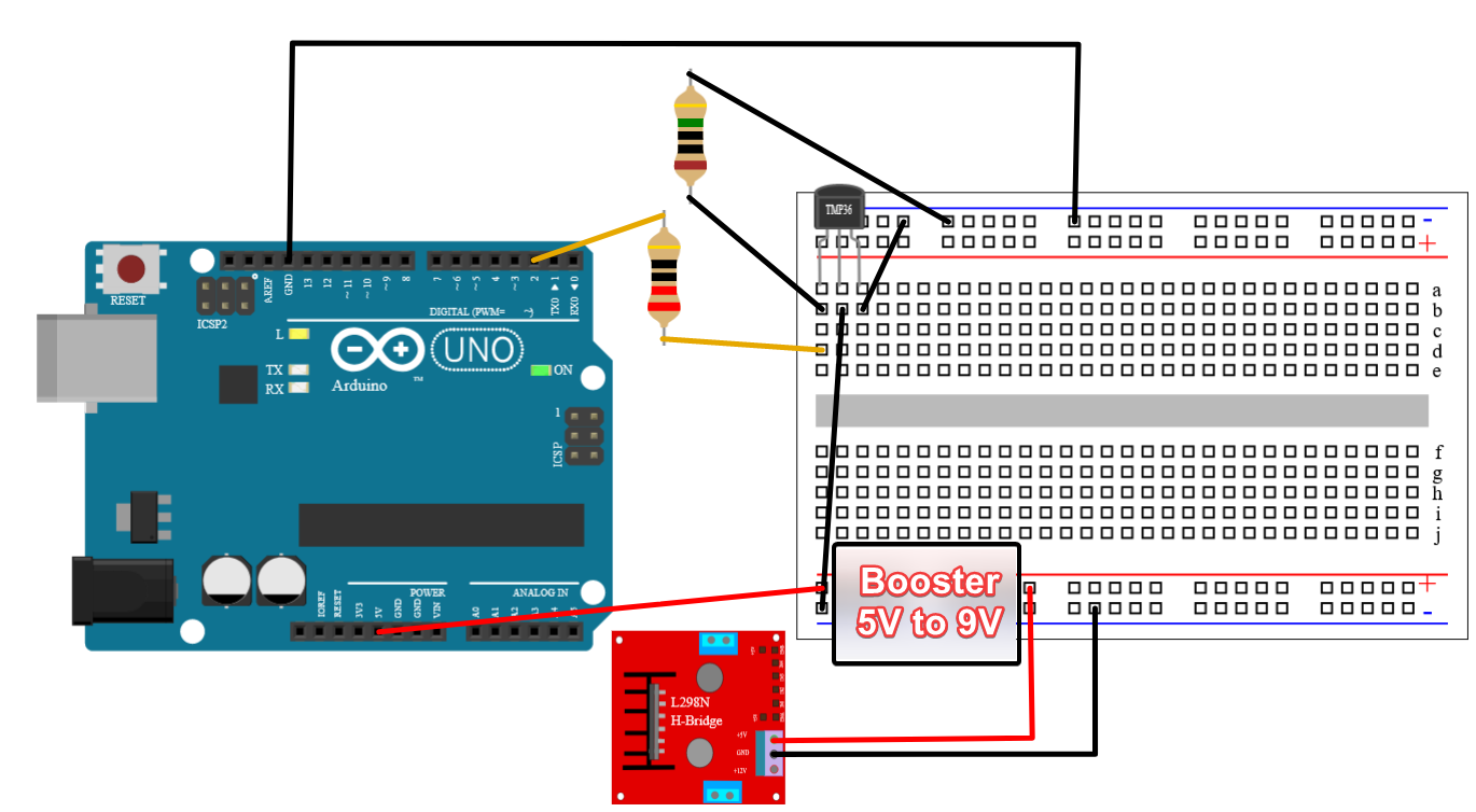
This is the correct and finally working wiring (ignore the lack of resistor to the LED):
I'm now experiencing another problem though.
When I'm plugging an LED it works fine with a simple blink sketch to pin 2.
When I'm replacing the LED with a Mini-L298N (h-bridge motor driver) the MOSFET stays always on. Between the L298N and the MOSFET there is a voltage booster 5 to 9V.
Although the used FDD8447L is a logic level MOSFET, 3V3 coming from ESP32 might be not enough. If you look at the datasheet the Vgs threshold voltage can be as high as 3.0V. That is where only 250uA Ids can flow!
Just tested it out with an Arduino Uno connected via USB. The 5V out drops about 2.2 volts from drain to source in this configuration. (the mosfet is GSD, not GDS)
Now, can you please post a copy of your circuit, in CAD or a picture of a hand drawn circuit in jpg, png?
Hand drawn and photographed is perfectly acceptable.
Please include ALL hardware, power supplies, component names and pin labels.
In particular, label the gate, drain and source pins, cut and paste images do not show everything.
It's true that a Darlington type NPN transistor like TIP122 could be easily switched with a GPIO. Darlington type transistors have very high current gain, for 2A collector current TIP122 would only need ~1mA base current!
But wouldn't be the CE saturation voltage too high for this application? At 2A it would be around 1V.
Even if the solenoid would be okay with the voltage drop, the transistor would dissipate 2W, which is ~120°C temperature rise on the transistor (without added cooling).
With a correctly chosen and switched MOSFET, the dissipation would be maximum 0,5W.
I'm now experiencing another problem though.
When I'm plugging an LED it works fine with a simple blink sketch to pin 2.
When I'm replacing the LED with a Mini-L298N (h-bridge motor driver) the MOSFET stays always on. Between the L298N and the MOSFET there is a voltage booster 5 to 9V.
The MOSFET enables power to the H-bridge. I need this on/off configuration because the H-bridge dissipates power when powered and of course this is not acceptable in a future battery powered configuration.