FT810 with Uno R4 Minima - doesn't work

I edited the previous message instead of replying in a new one. Wow, the TFT doesn't seem to respond. Let's try something else

1 Load the example in R4Minima, the eeprom_clear example from the EEPROM library

2 Load the eeprom_read example again. Zeros should be displayed instead of 255.

3 I updated GDSTx to make the touch panel of your FT810 responsive. Load example 3.BT817/VectorTactil_BT817

At this point the screen should respond in some way.

4 Load the eeprom_read example again and take a screenshot of the serial monitor

Hi @TFTLCDCyg I have followed Your guide list:

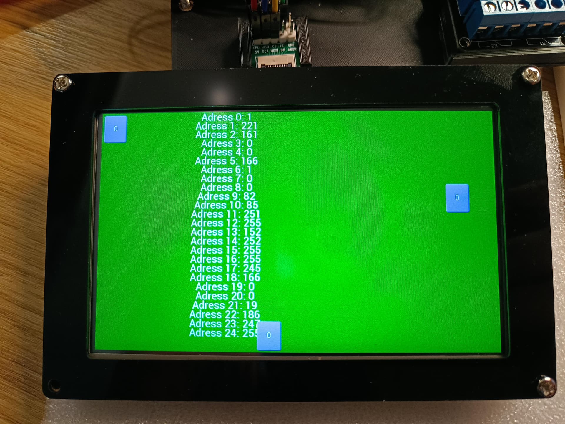
My results are (first screen is after eeprom clear and the second is eeprom_reading after VectorTactil_BT817 sketch was in use):

The screen is black as it was before, but I assume that those numbers in eeprom are telling us that the screen is responding some or another way. Are those numbers telling You anything?

BTW. I must agree with you I was maybe not enough carefully when operating with the cables, could be some static electricity. On Tuesday I should get second screen of FT810 then I will test it and see if it will work, I bought also anti static gloves just in case :slight_smile:

This is what I was afraid of, the backlight seems to be the problem, since it loads the sketch well and records the vector in the eeprom, if it had remained at zero it would indicate a problem with the TFT chip, however apparently it detects it but the backlight driver stopped working.

Just as other screens for Arduino are very sensitive to static electricity, it is an issue that is never talked about and until it happens you realize how delicate they are. An antistatic bracelet is best

If you allow me some advice and you want to move forward using this type of screens, the one that has helped me the most in projects is this NHD 5.0 ​​800480FT CSXP-CTP. I know it has been difficult for you to get your TFT and your Arduino board, however if you are looking for more operating power I recommend these two MCUs; teensy 4 or teensy 4.1, the difference between the two is that 4.1 has more GPIO and has a built-in SDIO reader. I spent many years together with several friends migrating the gameduino 2 library so that it can work with SdFat instead of SD, as a result we have GDSTx. Since it is the hardware that I know in depth, I can tell you without hesitation that you only have to connect the pins between the teensy 4.1 and the TFT, on a robust base and you will forget to worry about the screen, the only care will be to avoid static electricity at all times.

And the truth is that I was very surprised, I think I wasted many years trying to make my GPS project work on screens that do not have enough graphic capacity, honestly I have not found anything that even remotely resembles them.

I recommend the FT813 chips more, especially the NHD ones, the audio conversion circuit is the best of all, with almost no background noise. BT817 is a great advance but the PC audio AI of Realtek chips eliminates audio signals that it considers too noisy, distorting the sound in videos.

Let's hope your new TFT works without problems

Good evening all :slight_smile:

I have received the new TFT screen so I continue my project.
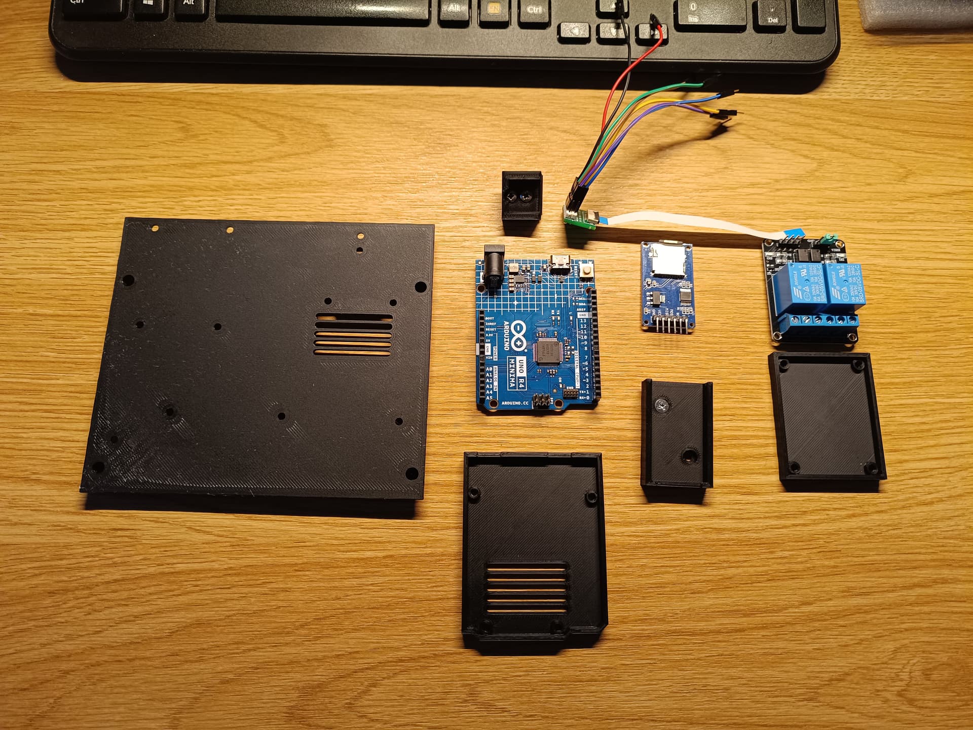
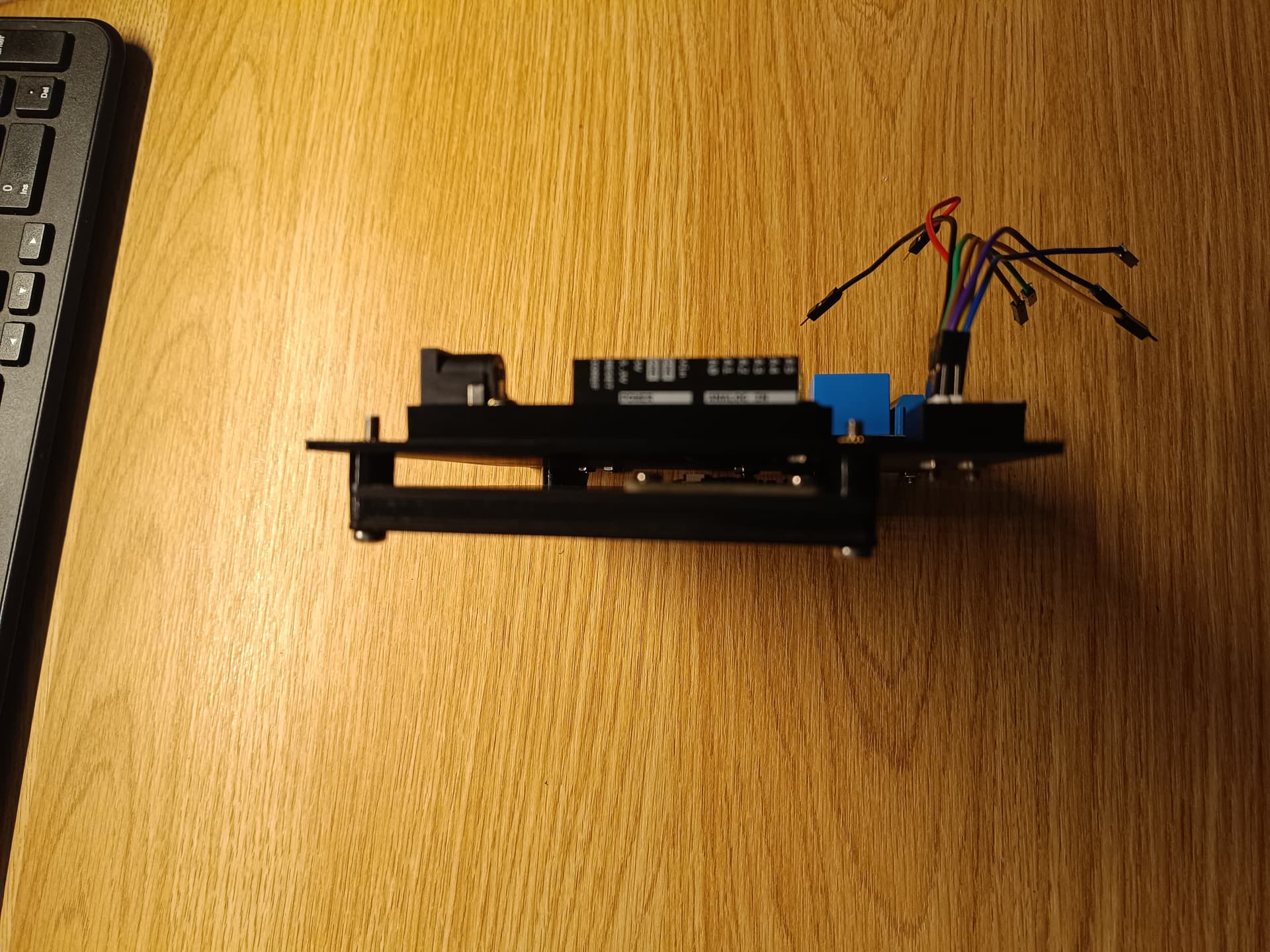
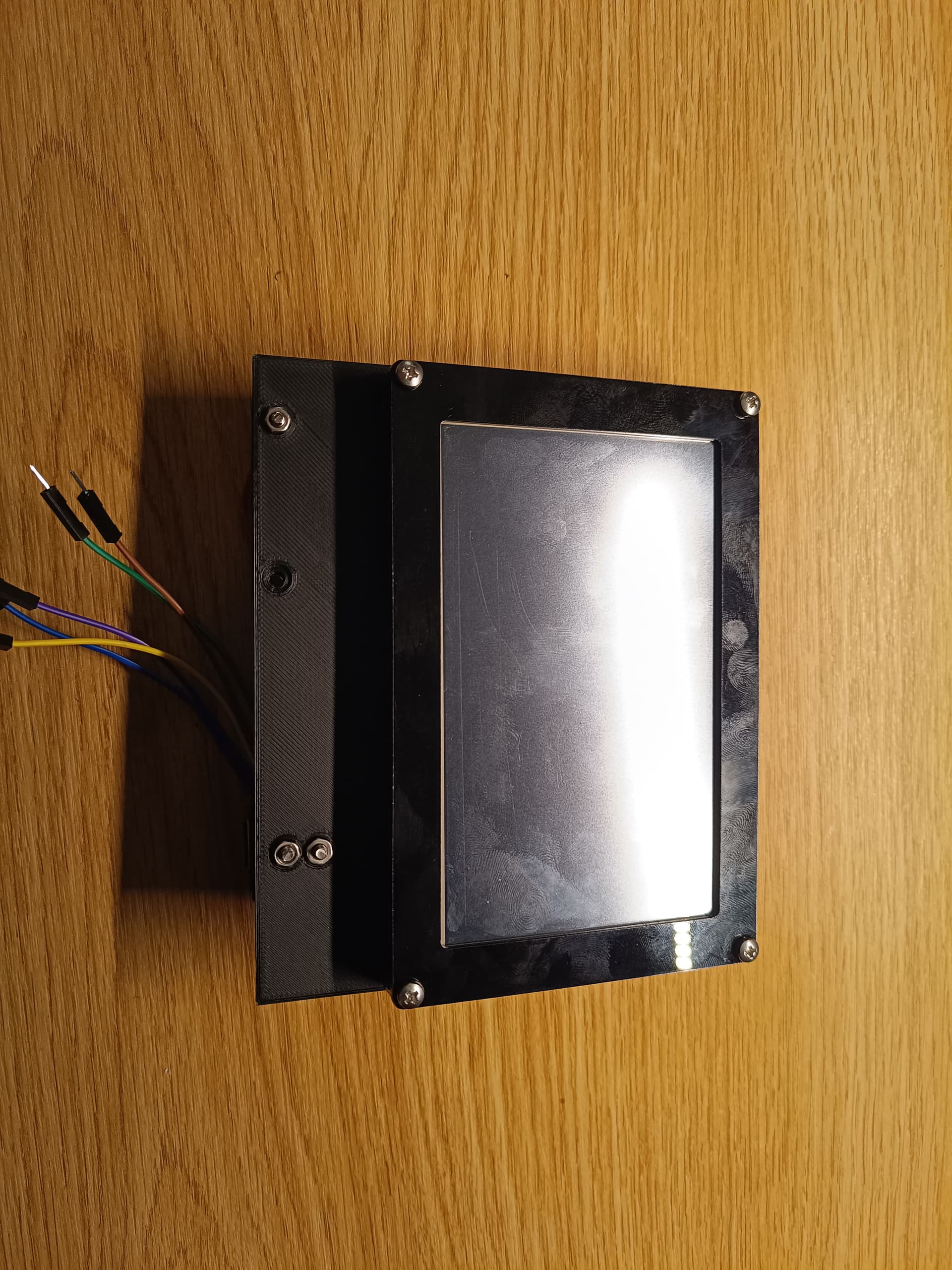
In the mean time I manage to prepare some 3d printed plate/holder for my modules Arduino etc. and everything attached to my 5 inch TFT screen.

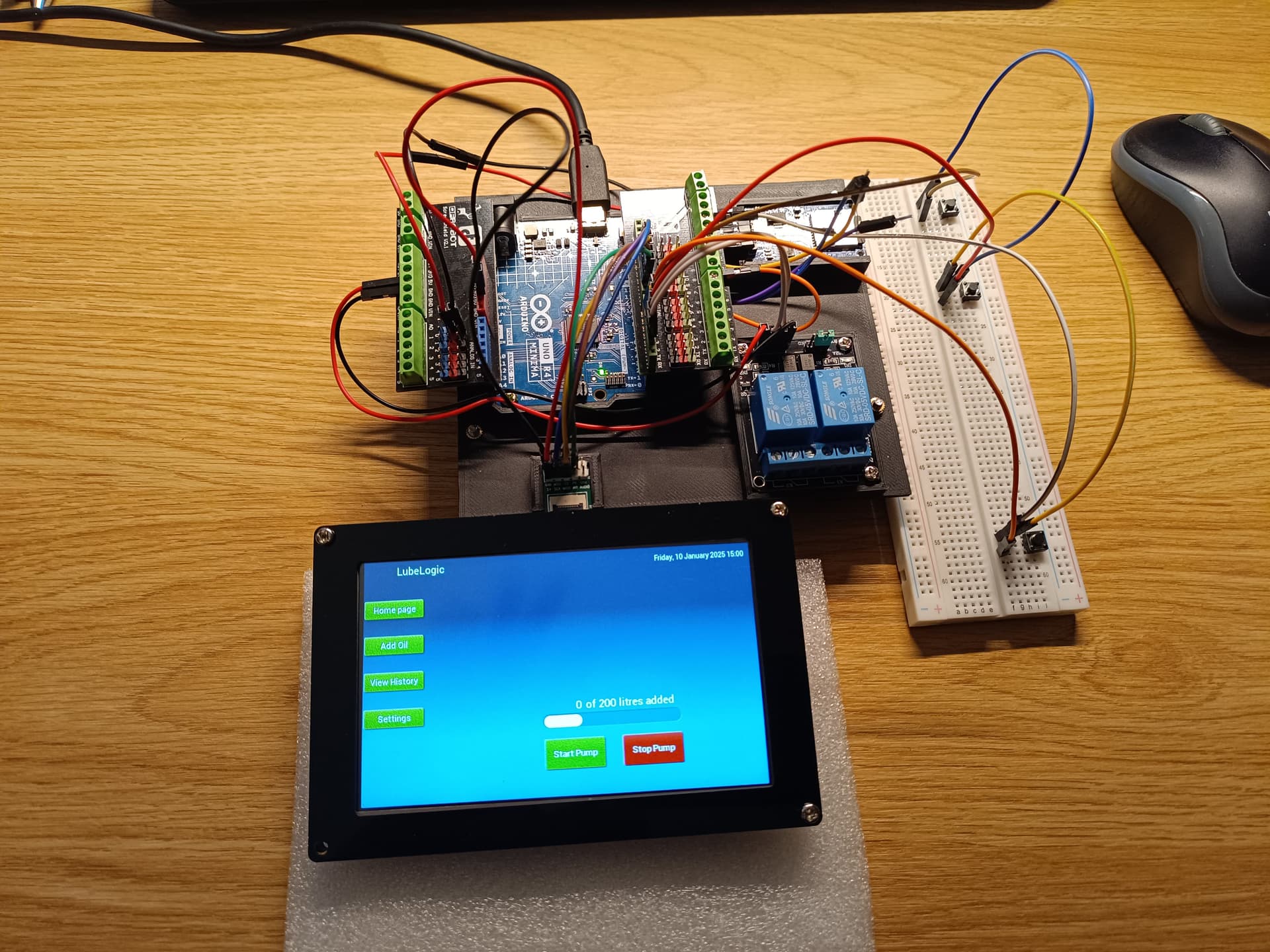
I managed to connect the screen and seems to be working

Thank You one more time for all your advice's and help especially @TFTLCDCyg

If you have taken advantage of the time, it is already in its support. How good it turned out. Congratulations.

Many questions to ask:

Were you able to get the touch panel working with the settings from the latest version of GDSTx?

Did it work?, really?

Hi @TFTLCDCyg, yes touch panel is working I used Your VectorTactil_BT817 sketch. However I needed to add cmd_calibration() after begin() otherwise it did not worked.

Anyway this is the result:

Now I am struggling with some good example how to write proper efficient "display list". I need to figure out when to use save_context, etc.

One issue which I have and maybe You can somehow advice. I use the SD Card Module together with TFT. I use the same MOSI, MISO and SCK pins for it but with different CS pins. So at the beginning it did not worked but I have found in internet some advice that need to change both CS pins to HIGH at the setup stage before initiating either TFT or SD card. That started to work. But I am struggling with changing between. I did something which work more or less but I am not sure if this is correct way to do it.

Basically each time when I draw something with GD library and want to for example read something from the SD card I change TFT screen CS pin to HIGH, and opposite when I move back to TFT GD library code I change SD card CS pin to HIGH. For example (only some parts of the code). I use your library GDSTx.h and SdFat.h

void setup() {
  // Before GD.Begin()
  digitalWrite(TFT_CS, HIGH);
  digitalWrite(SD_CS, HIGH);
...
  GD.Begin();
  GD.self_calibrate();
  digitalWrite(TFT_CS, HIGH);
...
  sd.begin(SD_CS, SPI_HALF_SPEED);
  digitalWrite(SD_CS, HIGH);
}

GD.ClearColorRGB(0x100020);
GD.Clear();
...
GD.Swap();
digitalWrite(TFT_CS, HIGH);

myFile.open("nameOfTheFile.csv", O)RDWR | O_CREAT | O_AT_END)
myFile.println("Something");
myFile.close();
digitalWrite(SD_CS, HIGH);

The problem is when I want to use for example SD card inside of the GD display list. Then I get an error that I have no card or something. Is there a better way to handle with selection of the currently used SPI device?

Thank you in advance for any advice.

And if you have some good example/tutorial of some simple changing between screens menu sketch to recommend. I have programing guide from FTDI its ok but not too many examples. How to properly use it and when.

There are several things to fine-tune.

What pin SD-CS are you using it for the microSD card?

On the microSD card, what information do you need to store?

Regarding the touch panel, load the eeprom_clear example first.

Then load any example, without using the cmd_selfcalibrate statement. This should be enough to activate the calibration routine that will allow the new calibration vector to be stored.

Load the eeprom_read example and upload a screenshot to see if it takes effect and see if there is anything else to correct in the library

Hi,

What pin SD-CS are you using it for the microSD card?

My connections for the moment looks like this:

Arduino Uno4       TFT FT810 Screen      SD Card Module
Pin 13             SCK                   SCK
Pin 12             MISO                  MISO
Pin 11             MOSI                  MOSI
Pin 10             CS
Pin 9              PD
Pin 8                                    CS

So basically TFT and SD are using the same SCK, MISO, MOSI and TFT has pin 10 as CS and SD has Pin 8 as CS.

On the microSD card, what information do you need to store?

I want to store some data form my program in CSV files. Some strings and float, integers etc. Beside of that I would like to have some graphic elements for the GUI on the SD card to use with the TFT screen.

Then load any example, without using the cmd_selfcalibrate statement. This should be enough to activate the calibration routine that will allow the new calibration vector to be stored.

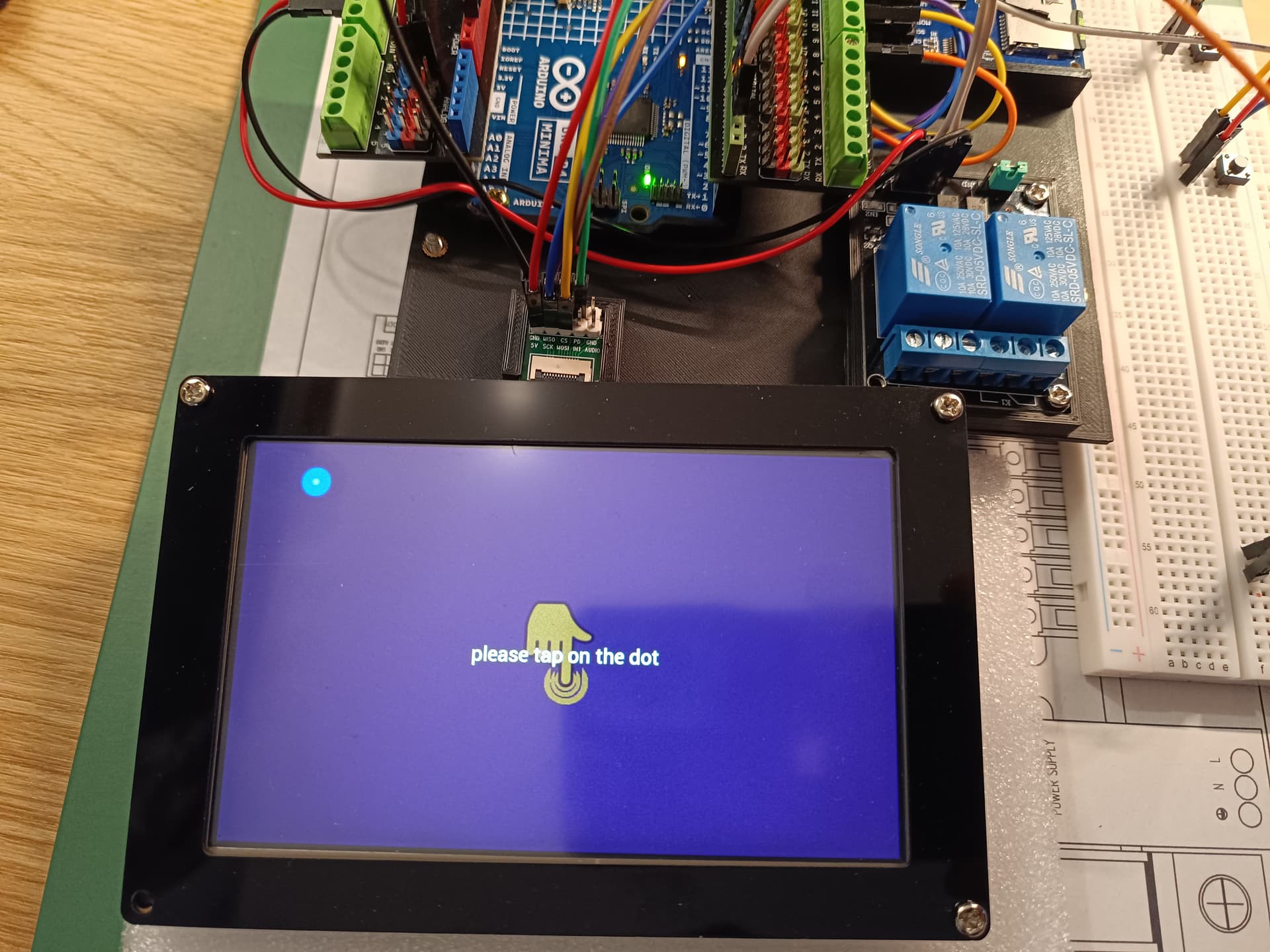
I did as above. I clear the eeprom and tried to start the VectorTactil_BT817 sketch from Your library. If I use it as it is, so without self calibration. It doesn't work. But when I add self_calibration it is working. Bellow 2 screens, one is when I started without self_calibration (left one) and the second with the self calibration (right one). I see all values are the same.

MicroSD

1 Ok I guess you want to store values ​​related to the devices you want to control. For those types of situations I suggest an external eeprom memory. There are some with very good speed, I mention this because I have tried to store data in the microSD memory of the teensy 4.1 and doing so interferes with the loading of multimedia files with GDSTx. The eeprom I used is this: 24FC512-I/ST.

2 Locate these lines in the GDSTx.h file

#ifdef ARDUINO_UNOR4_MINIMA
  	#if (SizeEVE==5)
		#define SetSPISpeed   36000000    // reducir al valor si la pantalla no enciende o es inestable con gráficos lineales contínuos y/o reproducción de videos
	#endif 
	
  	#if (SizeEVE==510)
		#define SetSPISpeed   36000000    // reducir al valor si la pantalla no enciende o es inestable con gráficos lineales contínuos y/o reproducción de videos
	    
	#endif 	
	
  #define SD_PIN 			      13         //SPI-1
  #define SetSDSpeed       	 	  24	
#endif

Debe quedar así:

#ifdef ARDUINO_UNOR4_MINIMA
  	#if (SizeEVE==5)
		#define SetSPISpeed   36000000    // reducir al valor si la pantalla no enciende o es inestable con gráficos lineales contínuos y/o reproducción de videos
	#endif 
	
  	#if (SizeEVE==510)
		#define SetSPISpeed   36000000    // reducir al valor si la pantalla no enciende o es inestable con gráficos lineales contínuos y/o reproducción de videos
	    
	#endif 	
	
  #define SD_PIN 			       8         //SPI-1
  #define SetSDSpeed       	 	  24	
#endif

Small finger error on the CS pin of the microSD reader, inside the library.

Minimum R4 EEprom

Regarding the calibration routine, please first clear the eeprom with the eeprom_clear example.

Load only this sketch:

#include <GDSTx.h>

void setup() 
{
 GD.begin();
}

void loop() {
  GD.ClearColorRGB(0x00aa00); 
  GD.Clear();
  GD.get_inputs(); 
    GD.cmd_text(GD.w / 2, GD.h / 2, 31, OPT_CENTER, "Hello world");
  GD.swap();
}

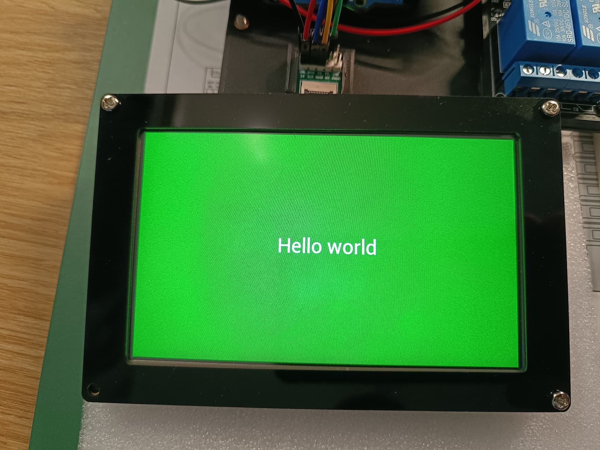
Please upload a screenshot of the first thing that shows on the screen.

Hi again :slight_smile:

So I did change of the pin definition in the library as You mentioned above.

I clear the eeprom memory with eeprom_clear sketch and first time after upload the program:

#include <GDSTx.h>

void setup() 
{
 GD.begin();
}

void loop() {
  GD.ClearColorRGB(0x00aa00); 
  GD.Clear();
  GD.get_inputs(); 
    GD.cmd_text(GD.w / 2, GD.h / 2, 31, OPT_CENTER, "Hello world");
  GD.swap();
}

I have received this screen:

I did calibration as it says and then I have received below screen.

When I restart Arduino after that I did not received calibration screen again it goes straight to Hello World screen.

Strange, when I was writing this message and program was running I have received this message:

I already realized that some settings were missing with the microSD, I updated the library again, added the change that we just mentioned for pin 8.

Try the calibration procedure again.

Since I don't have the R4 minima on hand, I'm trying to imagine how it works with the tests you're supporting me with.

After update of your library and during compilation of helloworld sketch from previous post i have received below compilation error:

GDSTx-main\GDSTx.cpp: In member function 'void GDClass::begin(int)':
GDSTx-main\GDSTx.cpp:140:82: error: 'SPI1' was not declared in this scope
    #define SD_CONFIG SdSpiConfig(SD_PIN, DEDICATED_SPI, SD_SCK_MHZ(SetSDSpeed), &SPI1)     //Bus SPI-1
                                                                                  ^
GDSTx-main\GDSTx.cpp:742:12: note: in expansion of macro 'SD_CONFIG'
  SSD.begin(SD_CONFIG);
            ^~~~~~~~~
GDSTx-main\GDSTx.cpp:140:82: note: suggested alternative: 'SPI'
    #define SD_CONFIG SdSpiConfig(SD_PIN, DEDICATED_SPI, SD_SCK_MHZ(SetSDSpeed), &SPI1)     //Bus SPI-1
                                                                                  ^
GDSTx-main\GDSTx.cpp:742:12: note: in expansion of macro 'SD_CONFIG'
  SSD.begin(SD_CONFIG);
            ^~~~~~~~~

exit status 1

Compilation error: exit status 1

So as I understood correctly i need to define SD_CONFIG in the sketch?

I am trying to support You as this is also my interest to have working library :slight_smile:
So I am happy to help as much as I am able with my knowledge and skills :slight_smile:

Go ahead with the help, it is welcome. I have been testing various options to enable access to microSD memory with the help of SdFat.

The original gameduino library has always incorporated the SD library into its core. This small aspect makes it too complicated to enable the screen functions and separate the functions of the external SD/microSD reader for loading multimedia files.

The SdFat library can work with several SPI buses at the same time, however they must be directed in some way.

The Rpi-Pico has two SPI buses 0 and 1. SPI0 is the default bus and does not need to be defined, it works with the default pins. The SPI1 bus must be called independently. I mistakenly thought that the minimum R4, having an Arm chip, would have several SPI buses defined, which from the results you obtained is not the case.

The arduino MEGA, and the arduino Due, have presented this challenge to me before and it seems that they share it with the R4 Minima.

The idea is to be able to enable access to the TFT with the advanced graphic functions of the FT813/FT810 chips with GDSTx, but also to be able to use an external microSD reader for multimedia with the SdFat library, which is much faster than the SD library.

Inside GDSTx.ccp instead of using this line:

#if defined(ARDUINO_UNOR4_MINIMA)                             //******************************************************Arduino UNO R4 MINIMA
   #include "EEPROM.h"
   #define SD_CONFIG SdSpiConfig(SD_PIN, DEDICATED_SPI, SD_SCK_MHZ(SetSDSpeed), &SPI1)     //Bus SPI-1
   SdFs SSD;                                                              //type 3   
#endif                                                       //*******************************************************Arduino UNO R4 MINIMA

It could be used like this:

#if defined(ARDUINO_UNOR4_MINIMA)                             //******************************************************Arduino UNO R4 MINIMA
   #include "EEPROM.h"
   #define SD_CONFIG SdSpiConfig(SD_PIN, DEDICATED_SPI, SD_SCK_MHZ(SetSDSpeed))     //Bus SPI-1
   SdFs SSD;                                                              //type 3   
#endif                                                       //*******************************************************Arduino UNO R4 MINIMA

Hi @TFTLCDCyg

I confirm, now I can compile the code and Helloworld is working fine. The calibration is only at first time, when EEPROM is clear, otherwise it seems that it keeps settings. So I think that's good.

I will now try to load some image from SD card for test.

BTW. Can I use library SD card functions to write/read the files, or it is only allowing to read images via function of the GSTx library?

Update
I tried some of the examples jpg_bench.ino and JPG_Load.ino.

I have sdcard inserted, system of the files is exFAT, i have copy of the file ToMicroSD all files are directly on card without catalogue.

First one (jpg_bench) is compiling but I am getting an error screen.

The second one (JPG_Load) i couldn't compile due to part of the code of Parametros.ino

  if(SizeFT813==35){GD.cmd_text(2, GD.h-12, 20, 0, "EVE chip: FT813@NHD-3.5-320240FT-CSXN-CTP");}
  if(SizeFT813==43){GD.cmd_text(2, GD.h-12, 20, 0, "EVE chip: FT813@NHD-4.3-480272FT-CSXN-CTP");}
  if(SizeFT813==5){GD.cmd_text(2, GD.h-12, 20, 0, "EVE chip: FT813@NHD-5.0-800480FT-CTXL-CTP");}
  if(SizeFT813==7){GD.cmd_text(2, GD.h-12, 20, 0, "EVE chip: FT813@NHD-7.0-800480FT-CSXN-CTP");}
  if(SizeFT813==51){GD.cmd_text(2, GD.h-12, 20, 0, "EVE chip: FT813@Riverdi RVT50UQFNWC000");}
  if(SizeFT813==71){GD.cmd_text(2, GD.h-12, 20, 0, "EVE chip: FT813@Riverdi RVT70UQFNWC000");}
  if(SizeFT813==52){GD.cmd_text(2, GD.h-12, 20, 0, "EVE chip: BT815@Matrix Orbital EVE3-50G");}

When I commented those lines i could compile the program but I am still getting same error as above.

SD card is working when I use examples from SdFat library.

Any idea what could be wrong?

I updated the jpeg_bench example.

The library shares startup functions of the same SPI bus, in theory both devices should respond well: the FT810/FT813 and the external microSD reader.

In cases where the SPI bus is unique, the GDSTx library configures the microSD reader using the correct instructions indicated by SdFat, but this start interferes with the previous start of the TFT. Similar situations have occurred on the teensy 3.2, arduino MEGA and arduino Due, in which the TFT and touch panel respond without problem.

On boards with several SPI ports this does not happen and the GDSTx library works 100% with SdFat.

I have a base library for ARM micros, before the adjustments for SdFat and that is part of the main gameduino23X library. I keep it so I can study it later, because with it it is possible to activate both devices, the FT813 and the microSD reader, without interfering with each other.

I have downloaded updated library and I have tested the jpg_bench sketch, it is compiling now, unfortunately it is still the same as before with error message.

BTW If You will be updating library maybe change SD spi config for Arduino Minima like You suggested above.

This is the version of the library before the adjustments with SdFat

Gameduino23.zip (438.2 KB)

It is adapted for R4 Minima, with the pinout you have used until now. The same files on the microSD memory are preserved. It has served me very well with the teensy 3.2, which is very similar to your R4 Minima.

1 Load eeprom_clear

2 Load eeprom_read

3 Load the jpeg_bench example

It should ask you for the calibration procedure. After that he won't ask for it again.
Take a screenshot of the images loading, it should be able to display on screen

4 Reload the eeprom_read sketch to see if the settings worked and the touch vector was preserved

Hello :slight_smile:

I just wanted to share my project result and one more time thank You all and especially @TFTLCDCyg for Your support.

So basically I finish my project using previously mentioned components. I am currently starting new project but this time will be on Teensy 4.1 and NHD TFT 7 inch screen.

So here it is the result of my challange with TFT Arduino and other components. I did not managed to use microSD module to read the images, so some of them I draw using primitives and some small of them I converted to arrays and write into memory.

Hopefully all the things which I have learned with project 1.0 I will improve will project 2.0 for sure I will like to make code more modular split into parts like logic, gui etc. Now I have everything in one file which is quite complicated to look for issues.

The video of my project:

CHIEFOIL PROJECT

Great, it turned out very well.

I continued working on the library to be able to enable access to the microSD reader of the R4 minima, but I have not been able to do it, it generates reading errors.

For image management, you can use the microSD reader that Teensy 4.1 has natively, you don't have to connect anything. The GDSTx library is precisely designed to be able to use this Teensy 4.1 component and get multimedia support for avi, jpg, bmp, jpeg files, as well as image arrangements in cells, assets or sprites.

MicroSD memories larger than 512 Gb can be used. So far I have tried a high-speed memory of 256 Gb in exFat format.

Copy the files from the MicroSD folder that accompanies the GDSTx library to a memory, place it in the SDIO reader of the Teensy 4.1 and load the multimedia examples

Thanks @TFTLCDCyg I also gave up with the SD card. But I did it otherwise.

I will try Your above suggestions and see what the outcome will be.

śr., 19 lut 2025, 18:00 użytkownik TFTLCDCyg via Arduino Forum <notifications@arduino.discoursemail.com> napisał: