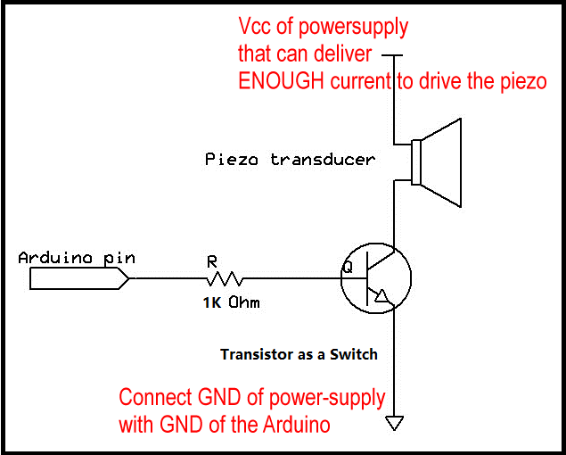
For P channel MOSFETs the Source goes to plus (positive).
You place the load on the Drain side.
If we are now talking about using a MOSFET used with an Arduino, the MOSFET needs to be a logic level type; some part numbers are shown on the schematic offered you in post #6.
If you need 12v to power the load, circuit H2 will work with the Arduino and using your MOSFET part number.
Here is another option that you can try.
2.5kHz tone for 500ms.
If the pieco pulls more than 20 mA it should not be connected directly to the IO-pins.
Hence the transistor.
toneAC is using two IO-pins.
With this the polarity can be changed. And this is indeed like an AC-voltage.
Again: if the piezo pulls more than 20 mA it should not be connected directly to the IO-pins like shown in the schematic of ToneAC. The schematic at ToneAC has a current limiting resistor.
If the piezo must be driven with more than 20 mA ToneAC would only work in conjunction with a H-Bridge
Then it will be easier to use an external powersupply with the voltage the piezo needs and a simple transistor
What is so hard about posting a circuit that suits the application
I recommend using a transistor over an MOS-FET in this application.
Depending on the current almost any small transistor will do
50 to 80 mA. BC238, BC547 lot's of 2N-types too
300 to 800 mA BC337 or similar
MOS-FETs are very sensitive about electrostatic discharge.
Slurp over a carpet with plastic-sole-shoes which will charge your body electro-static then touch one pin of the MOS-FET for 1/100 second !BANG! MOS-FET destroyed
Well, the circuit you posted (post#13) won't work for a piezo (which is basically a capacitor).
40kHz transmitters have AFAIK a minimum impedance at resonance of about 500ohm, so it should be fine to drive it between two Arduino pins. Can add 100ohm in series with the piezo to be sure.
Leo..
If the transducer is a piezo transducer electrically seen it is a capacitor.
500 Ohms means a current of
5V / 500 Ohm = 10 mA which is safe for an Arduino IO-pin
Though it might be interesting what the real current is. As driving the piezo from two IO-pins that change polarity
IO-pin 09 plus --------Transducer------- minus IO-pin 10
IO-pin 09 minus -----Transducer------- plus IO-pin 10
the suddenly reversing of the polarity causes a short peak-current.
A resistor in series with the transducer limits this peak-current