I was ask by someone to create an device which emits a 25kHz Ultrasonic Signal.
So I was wondering which components do I need for that?
I think I need this componets:
a Microcontroller, e.g Arduino Nano or ATtiny
a Ultrasonic Transducer something like a piezoelectric speaker
maybe a resistor to limit the current?
(The piezo would be connected to a digital pin of the microcontroller)
But I am not sure if my assumption is correct.
This would be the code I use to create the 25 kHz:
const int pin = 9;  // Pin connected to the transducer

void setup() {
  // Start generating a 25 kHz tone on pin 9
  tone(pin, 25000);
}

void loop() {
  // The tone function is non-blocking, so nothing is needed in the loop
}
Would that work like this or did I made some error?
Or 'a driver' to drive correctly the transducer.
The hc04 ( see the schematics ) for example uses a max232 ( uses its charge pumps to generate a differential signal ), like the idea.
Currenty I don´t have the hardware, but your are rigth maybe I could need an transistor to increase the current depending what hardware I need.
Does it make sense to use a transistor or should I use a MOSFET?
(The MOSFET should be more efficient and has less Leakage current or I am wrong here). Does it make a real difference if they get used 24/7?
Do you mean this one HC-SR04 Ultrasound Module Remanding meter Sensor for Raspberry Pi ? I was actually thinking if I could use that somehow or just try to get the parts I needed. The problem is I am not sure if the can handle the frequency so I put that idea in the trash bin. If that actually work I would try it.
The Max232 is if I understand that correctly used to change the signal to a higher voltage rigth?
I don't know of any piezo speakers that will go to 25kHz
First select your 25kHz transducer. Read the data sheet to determine how to drive it.
If you can't figure it out come back here.
Perhaps something like this. At least there's proper data for it. It depends how loud you want it to be. You could perhaps drive it with two anti-phase gpio pins to double the output voltage from peak ~= Vcc to peak ~= 2xVcc. Around the resonant frequency the impedance is > 1000 ohms, so you wouldn't need current limiting resistors to limit the current or transistors to boost the current.
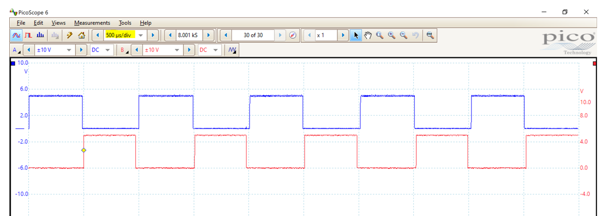
Anti-phase looks like this on an oscilloscope, this screen snip is for 1kHz, but the same idea would apply for 25kHz.
Speakers are bound to human hearing.
Piezo elements can reach much higher frequencies. As capacitors they may deserve current limiting resistors with low power GPIOs.
Ah ok I thougth because you recommended me a transistor that a mosfet should also work. So that driver converts it to the correct voltage and to AC?
Can I still use the code or do I need to do something completly different now?
I am new to the topic and just saw that some sell them. Because of that I assumed they exist. Since it is just an idea so far the parts can still change.
All the parts you will need and the code will depend on the transducer you select. No point in going any further until you select the transducer that is appropriate for your application.
Yes I think that is what I am looking for, can I change the volume somehow too like decreasing or increasing the voltage or is that fixed?
Do I create these anti-phase gpio pins with inverted PWM Signals or how can I get them?
It sounds like an interesting idea, I wonder if I also can implement that.
yes, the max232 is used to stepup voltage and to drive the transducer ( don't know if it is safe to drive directly from micro pins ).
The hc04 uses 40KHz transducers ( mesured 38KHz )
What is your intended usage ( for example why you need variable output amplitute, and do you need receiver too, do you need a pure sinusoidal output or a square wave is ok )?
The usecase is to send a ultrasonic signal and a smartphone should be able to receive the sound with the microphone. The signal does not get send the whole time only if a special event occures. The variable output is needed to test which volume is needed to to receive the signal.
I think the wave doesn´t matter since it is only important to receive the ultrasonic signal with the smartphone.
In my application (a 1kHz beep for a geiger counter) I change the volume by changing the pulse width.
I'm doing this on an ATtiny85 running at 8MHz. I do it in C++ using digitalWrite() and delays using micros(). I don't have any experience of using PWM other than basic things like LED brightness control. I don't know about inverted PWM.
The ToneAC library does that and is supposed to be capable of generating ultrasonic frequencies. All you need is a piezo transducer and a 220 Ohm series resistor to limit the pin current. I believe the library works only with certain AVR-based Arduinos (for certain with the ATmega328 series).
For best results and highest volume, pick a transducer with resonant frequency about equal to the desired output frequency.
Well first you need to determine the maximum "volume" you will need. If you buy a transducer that can't produce the volume that you need, then you just wasted your money.