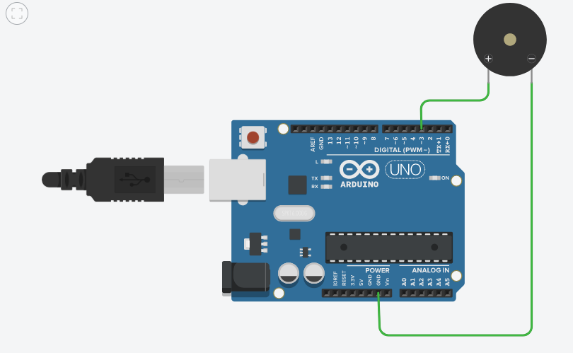
Hi. I'm trying to apply the topics of physics to Arduino. As part of it, I've tried to apply the General Wave Equation using an Arduino Nano and a buzzer.
// WAVE EQUATION 2.0
//Author: RASA911216
//Wave value.
float wave;
//Wave angle.
int x = 0;
//Wave power.
int intensity = 250;
//Wavelength.
float lambda = 1;
//Wave period.
float T = 440;
//Time.
int time = 0;
//Where the buzzer is connected.
int PWM = 3;
//Wave phase angle.
int phi = 0;
void setup() {
//Start Serial Communication.
Serial.begin(9600);
pinMode(PWM, OUTPUT);
}
void loop() {
//Increase angle and time value.
x = x + 1;
time = time + 1;
//Wave constant in radians.
float k = ((2 * PI)/lambda) * 71 / 4068;
//Angular frequency using radians.
float omega = ((2*PI/T) * 71) / 4068;
//WAVE CREATION.
wave = intensity * cos((k * x) + (omega * time) + phi);
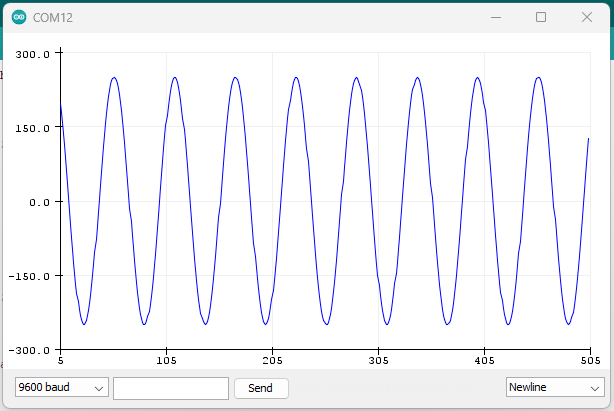
//Plot the wave value.
Serial.println(wave);
/*Serial.println("###############################");
Serial.print("k constant: ");
Serial.println(k);
Serial.print("Omega constant: ");
Serial.println(omega);
Serial.print("x value: ");
Serial.println(x);
Serial.print("Time: ");
Serial.println(time);
Serial.println("###############################");*/
//Move the range of the values to avoid negatives.
float wavePWM = intensity * (cos((k * x) + (omega * time) + phi) + 1);
//Send the wave value to the buzzer as an analog value.
analogWrite(PWM, wavePWM);
//Wait 100 miliseconds before processing again.
delay(100);
}
And tried to match common tones like 440 Hz and 800 Hz and the musical notes. But no matter how much I modify the wave period, I don't get the tone.
I also don't want to use the tone libraries because the goal is to match the tones using the general wave equation from scratch. Are there any suggestions that could be made to the code?
There are three major problems with your approach. The first is that you are printing values in the loop, using an extremely low serial Baud rate of 9600, and that takes 1 millisecond to print each and every character.
The second is for the audio to match the tone frequency, the signal amplitudes have to be output at time intervals that match the audio waveform sample rate. That won't work if you are printing, and the loop timing interval needs to take into account the time required to calculate cosine and do other math.
The third is that a buzzer is not a speaker. To generate clean sine/cosine tones, you need an audio amplifier (with capacitive coupling, a low pass filter to remove the PWM noise, and a volume control) and a speaker with a separate power supply.
I see, so the print is what is harming the process. Didn't expect it to impact it so much.
And is there any resource to see how the tone command achieves this?
#include "pitches.h"

#define BUZZER_PIN 9

int melody[] = {
  // Notes goes here
};

int durations[] = {
  // Notes duration goes here
};

void setup()
{
  pinMode(BUZZER_PIN, OUTPUT);
}

void loop()
{
  int size = sizeof(durations) / sizeof(int);

  for (int note = 0; note < size; note++) {
    //to calculate the note duration, take one second divided by the note type.
    //e.g. quarter note = 1000 / 4, eighth note = 1000/8, etc.
    int duration = 1000 / durations[note];
    tone(BUZZER_PIN, melody[note], duration);

    //to distinguish the notes, set a minimum time between them.
    //the note's duration + 30% seems to work well:
    int pauseBetweenNotes = duration * 1.30;
    delay(pauseBetweenNotes);

    //stop the tone playing:
    noTone(BUZZER_PIN);
  }
}
Because like in this code it seems to be able to match specific frequencies but I wonder if its related to the General Wave Equation at all or uses another method.
The tone command source code is available, and you are welcome to look at it.
It sets up a hardware timer to generate a square wave at approximately the correct frequency.
Accurately reproducing sine waves, or other general audio signals is very processor intensive and requires very high CPU clock rates, or specialized DDS (direct digital synthesis) hardware.
Sometimes a piezo transducer (speaker) is mis-named as a "buzzer". A transducer will work with tone() to generate different frequencies and that's a quick way to check what you have.
Note that piezo speakers/transducers are "tweeters" and they don't reproduce low (bass) frequencies.
PWM is NOT true analog. It can "simulate" analog to control the speed of a motor to make an LED appear dim.
At a high-enough PWM frequency it can be used for audio but it's not ideal. The default PWM frequency is around 400Hz which is a problem because you can hear the PWM itself and it's not going to handle audio signals near or above that frequency. There are ways of increasing the PWM frequency but I've never done it.
For digital audio, the wave is represented by a series of samples and you need a known sample rate. This Digital Audio Fundamentals tutorial may help to get you started.
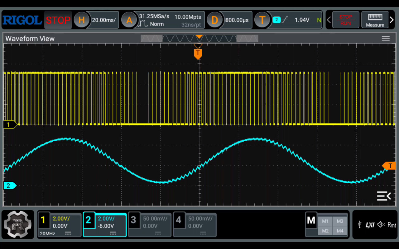
I have got a low pass filter connected to the output of pin 3.
My filter using a 10kΩ resistor and 1µF capacitor has a cutoff frequency of around 16Hz.
The filter will only pass frequencies below it's cutoff frequency without attenuation.
A frequency of around 10Hz is about the highest frequency that can be generated using this filter with a cutoff frequency of 16Hz and a 490Hz PWM signal.
Pre-calculate the values from your wave equation for a single cycle and put them into an array. This removes the time it takes to do the floating point trigonometry expressions. This makes a big difference.
To speed up the PWM do this in the setup function:-
void setup(void){
// Set PWM  Timer2 to a frequency of 25K0Hz.
 TCCR2A=0b00110010;
 TCCR2B=0b00010001;
 ICR2=32;
 OCR2B=16;
}