Hi, I'm new to this. I want to input 3 signals from 3 relays to nodeMCU. The signals come from 3 electrical motors via their contact points to relays. and from relays, I need to take 3 inputs to know which electrical motor is currently running. Is there a sample code that I could use?
A relay is nothing more that a switch or button. So you can use digitalRead() to read the them.
I assume that you know what you're doing at the electrical side of things. If not, post the specs / user manual of the motor. The relay contacts might e.g. carry a voltage (your description does not make that clear) that can be deadly for your NodeMCU.
Your topic has been moved to a more suitable location on the forum. Installation and Troubleshooting is not for advice on (nor for problems with) your project.
Motors are electrically very noisy , so if you have no spare contacts , drive 3 relays from the motor side of your contactor /motor relay .
Use the contacts of these new relays as your inputs , with a 1k pull up resistor .
Hi, thank you for the reply! yes, the relays output 5V. I do have other engineers who guide me through the electrical side of things as well. I just need a way to input the signals from the relays to nodeMCU. Its been a while since I last did Arduino. I remember using pullup resistors and whatnot. Just need some guidance on this before I start. Like a sample code to a basic input from relays to the nodeMCU.
yes I have already wired from the electrical contactors to 3 other separate relays. Is there a source that I could refer to input a signal from relays via pullup resistors? Or a sample code?
upload a schematic showing the wiring of the system , power supplies, etc
5V will be a killer for the NodeMCU; you'll have to reduce it to 3.3V using e.g. a voltage divider.
If your relay outputs 5V when activated and nothing when not activated (your input will be floating), you need a pull-down resistor. The voltage divider will take care of that.
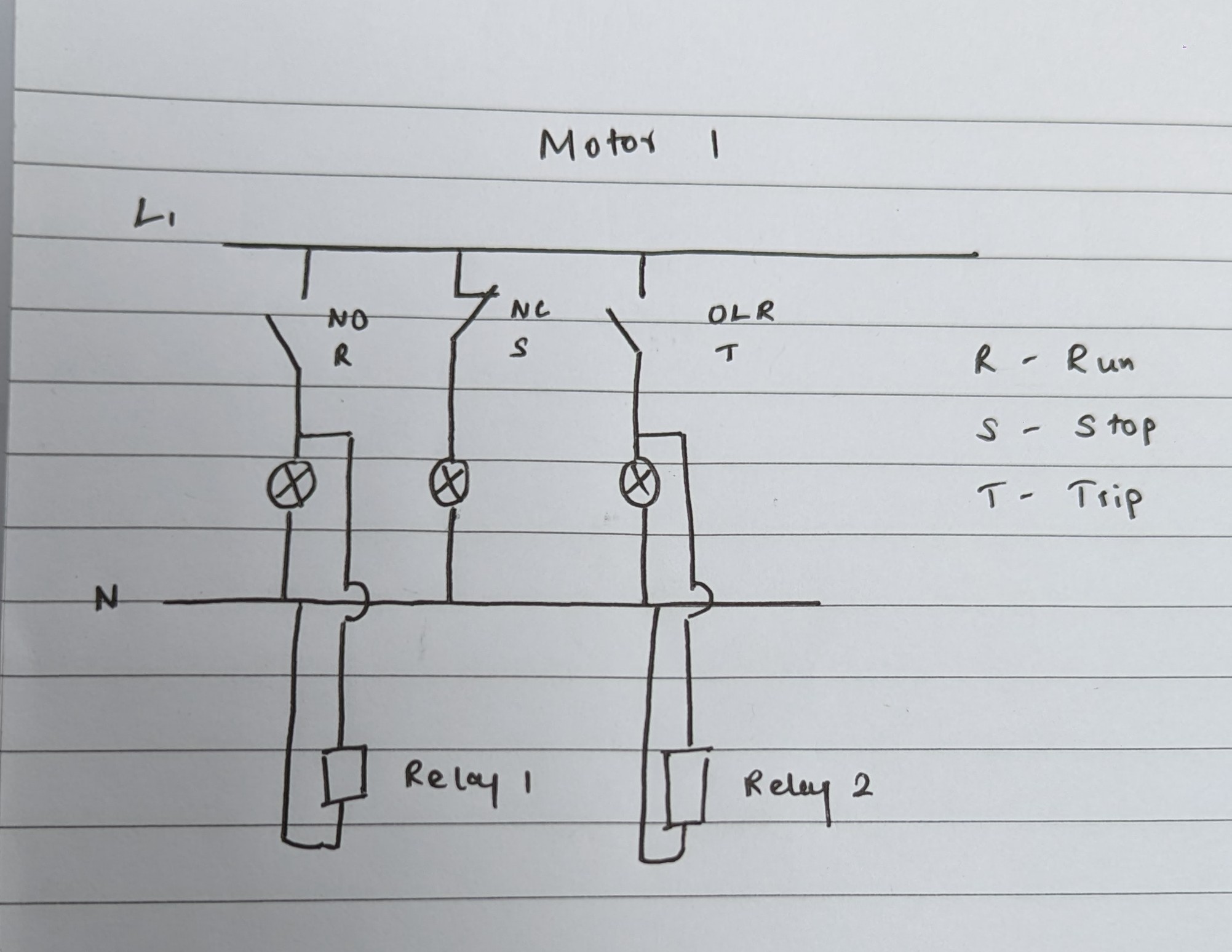
so this is just one diagram for motor 1, the same exact connection for 2 other motors. so I have taken a signal from between the contact point and the indicator to a separate relay for the RUN signal and another from the TRIP signal. for the stop signal I can code if either of those it should be stop.
if all you need is to detect if the motors are on or off could you use opto- isolators
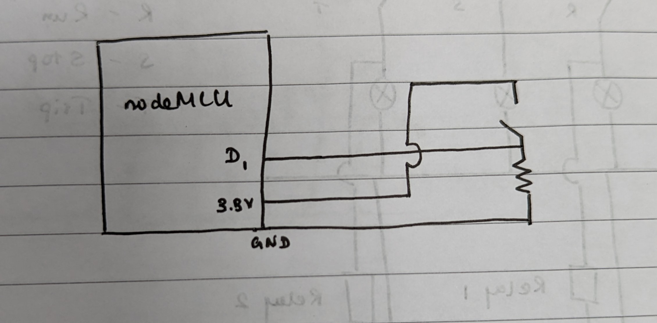
later I need to expand this system. There is a pressure sensor and a flowmeter. ill need to remotely monitor these as well. just for the start, I was thinking of the 3 motors. so this is the diagram I came up with for the relay and the nodeMCU. will you be able to help me with the code for a input signal from the relay?
Hello
Use optocouplers to electrically isolate the systems.
Hi, does anyone know how to read if the relay is on or off in nodeMCU? the relay is outputting 3.3V
Hi,
Won't the relays work for this system?
Your two topics on the same or similar subject have been merged.
Please do not duplicate your questions as doing so wastes the time and effort of the volunteers trying to help you as they are then answering the same thing in different places.
Please create one topic only for your question and choose the forum category carefully. If you have multiple questions about the same project then please ask your questions in the one topic as the answers to one question provide useful context for the others, and also you won’t have to keep explaining your project repeatedly.
Repeated duplicate posting could result in a temporary or permanent ban from the forum.
Could you take a few moments to Learn How To Use The Forum
It will help you get the best out of the forum in the future.
Thank you.
Hi really sorry regarding that, but the previous questions were related to the project. I wanted to know a few details regarding to the software side of things.
Or
From the schematic in post #10, they do not output anything.
Which one is it ??
How about digitalRead(D1) for your software / code question.
Hi all, so I came up with a solution with blynk iot. But I'm not sure if I have come up with the most efficient way of coding the program, let me know if I can improve anything on this. Also, the pins are supposed to receive a voltage input, but the nodemcu monitored the pins always high when it was configured as input, and strangely I tried them as output, then the code worked. Let me know if I done something stupidly incorrect here. thanks for the previous suggestions helped me a lot!
#define BLYNK_PRINT Serial
#include <ESP8266WiFi.h>
#include <BlynkSimpleEsp8266.h>

#define BLYNK_TEMPLATE_ID "TMPLD3oS8gML"
#define BLYNK_TEMPLATE_NAME "TEEJAY FIRE PUMP"
#define BLYNK_AUTH_TOKEN "taeaGqlQkB2uUb5HPYxgoF0PDzFS2eIt"

char auth[] = BLYNK_AUTH_TOKEN;
char ssid[] = "Pixel 6 pro";
char pass[] = "12345678";

int stateJR;
int stateJT;
int stateJS;

int state1R;
int state1T;
int state1S;

int state2R;
int state2T;
int state2S;


int status;
int status1;

const int pinJR = D0;
const int pinJT = D1;
const int pin1R = D2;
const int pin1T = D3;
const int pin2R = D4;
const int pin2T = D5;

void jokey()
{
 if(digitalRead(pinJR) == HIGH){
    stateJR = 1;
  }
  else
  {
    stateJR = 0;
  }
  if(digitalRead(pinJT) == HIGH){
    stateJT = 1;
  }
  else
  {
    stateJT = 0;
  }
  if(digitalRead(pinJR) == LOW & digitalRead(pinJT) == LOW){
    stateJS = 1;
  }
  else
  {
    stateJS = 0;
  }
}

void electric1()
{
 if(digitalRead(pin1R) == HIGH){
    state1R = 1;
  }
  else
  {
    state1R = 0;
  }
  if(digitalRead(pin1T) == HIGH){
    state1T = 1;
  }
  else
  {
    state1T = 0;
  }
  if(digitalRead(pin1R) == LOW & digitalRead(pin1T) == LOW){
    state1S = 1;
  }
  else
  {
    state1S = 0;
  }
}

void electric2()
{
 if(digitalRead(pin2R) == HIGH){
    state2R = 1;
  }
  else
  {
    state2R = 0;
  }
  if(digitalRead(pin2T) == HIGH){
    state2T = 1;
  }
  else
  {
    state2T = 0;
  }
  if(digitalRead(pin2R) == LOW & digitalRead(pin2T) == LOW){
    state2S = 1;
  }
  else
  {
    state2S = 0;
  }
}


void setup()
{
  pinMode(pinJR, OUTPUT);
  pinMode(pinJT, OUTPUT);
  pinMode(pin1R, OUTPUT);
  pinMode(pin1T, OUTPUT);
  pinMode(pin2R, OUTPUT);
  pinMode(pin2T, OUTPUT);
  Blynk.begin(auth, ssid, pass);
}

void loop()
{
  jokey();
  electric1();
  electric2();
  Blynk.virtualWrite(V0, stateJR);
  Blynk.virtualWrite(V1, stateJT);
  Blynk.virtualWrite(V2, stateJS);
  Blynk.virtualWrite(V3, state1R);
  Blynk.virtualWrite(V4, state1T);
  Blynk.virtualWrite(V5, state1S);
  Blynk.virtualWrite(V6, state2R);
  Blynk.virtualWrite(V7, state2T);
  Blynk.virtualWrite(V8, state2S);
  Blynk.run();
  /*Serial.begin(9600);
  status = digitalRead(pinJR);
  status1 = digitalRead(pinJT);
  Serial.println(status);
  Serial.println(status1);
  delay(100);
  */
}
Also, any suggestions to get a pressure reading on an output pipe which is usually measured at 10 bar and may vary to 4 bar?
This topic was automatically closed 180 days after the last reply. New replies are no longer allowed.