Hi. Let's suppose I have an Arduino board and it has a dedicated battery with 5v. And then suppose I connect the negative of the battery that is connected to the Arduino to the positive of a second 7 Volt battery. Now if one of the pins of the Arduino is set to high, will the potential difference between the output pin and negative of the second battery be equal to 12 Volt? Regarding the component protection let's assume that the current that is going through the terminal is about 50mA. Will it work? Will it damage the Arduino board?

I moved your topic to an appropriate forum category @anon2761406 .
In the future, please take some time to pick the forum category that best suits the subject of your topic. There is an "About the _____ category" topic at the top of each category that explains its purpose.
This is an important part of responsible forum usage, as explained in the "How to get the best out of this forum" guide. The guide contains a lot of other useful information. Please read it.
Thanks in advance for your cooperation
Definitely. Not a good idea.
It is better to power both the Arduino and the other thing from a 12V supply, using a 5V stepdown regulator for the Arduino, with a common ground for 5V and 12V.
Regarding the component protection let's assume that the current that is going through the terminal is about 50mA
Let's not.
Ok, but will it work? Does it not harm the Arduino? Will it not shut down that pin if the microcontroller senses the presence of a voltage more than 5 Volt?
No.
No, it does harm the Arduino.
No.
There is no such mechanism in any processor to do this.
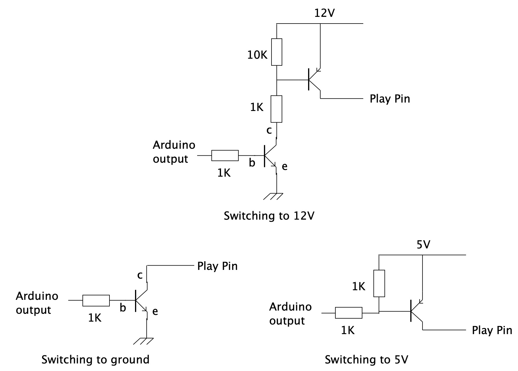
If you want to control a voltage higher than a processor's voltage rail then you have to switch it using the top circuit of this diagram. The "play pin" is the high voltage output.
1 Like
What does "will it work" mean? You didn't label your drawing, but from your description the 12V??? would actually measure -2V and it won't damage anything if you leave it as shown.
If you bridge the "12V" e.g., with a resistor then you're sending -2V into an Arduino pin and that's not going to end well.
Yes.
Now consider what the voltage will be when the outout is set to LOW
1 Like
Thanks Jim! You are correct, it will be -2v, but it wont matter in the scenario I apply it. . Here, I probably should have elaborated in more detail. So here is the project. I have to answer Grumpy Mike before he gets grumpier ![]()
More nonsense. Explain what you are actually trying to do.
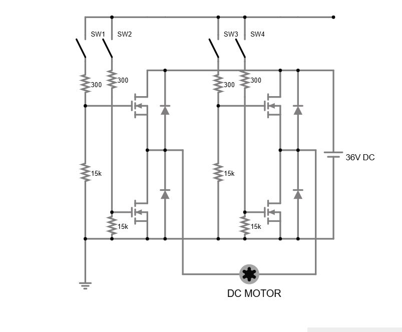
Thanks Mike! The Arduino output is supposed to drive a Half-Bridge similar to the one I post in the picture. Now, the problem that I cannot solve, is providing 10-11 volts to the gates of the MOSFETs. So, instead of SW1,SW2,SW3,SW4, the Arduino logic must be amplified to the required level and those switches are just for demo and testing in simulator. I kinda have a vague idea that transistors can do it but I don't know how to integrate it into the diagram and how to share the ground of 5v logic and 12 driver and 36v power supply for the motor. I know that 2 buck convertors can give me the 12v and 5v from the same 36v power supply but here is where I get confused. I also know that there are gate driver ICs like IR2104 etc. but they need a shut down pin as well and my project is a bit bigger and I need to be thrifty with pins, but IR2104 is not gonna change the scenario because it also takes 6 pins if I have a 3-phase Half_bridge . On the other hand, I just need to learn how to implement the idea without ICs which increases my knowledge of hardware. The top one with 2 transistors looks like the answer, but can it be simpler? Like one transistor? Thanks for your time
I did not say it would and it wiil not. When the output is low, the output pin is connected to ground or in your case the junction of the 5V minus and 7V plus
1 Like
Use the first circuit in post #5.
It really does help to supply information about your project, and take time to read and understand the responses to your questions.
True, but I thought that if Vg goes to equal or even below Vs, the gate will remain shut. Is that correct?
PS. In the case of N-Channel MOSFETs
No.
I must have missed that picture because the one in the first post told me nothing.
What is the part number of this half bridge?
Driving a motor with a half bridge requires much more than just a few transistors, depending what you want to do with it.
I have used a SN754410 dual half bridge to drive a motor, it has a logic power supply 5V, and a separate motor supply voltage which can be 12V, in fact up to 36V.
But it requires way more extra circuitry to enable it to work like you would want. This is the diagram of that motor control.

This circuit was for driving a motor, to push a rod to a point defined by a limit switch. With the motor being reversed to withdraw the rod to the initial position with exactly the same software command.
1 Like
It is a home-made bridge, 6 MOSFETs, most likely i will go with IRFZ44, 6 1N4007 for protecting the MOSFETs from motor induction kick-back, 9 resistors.

I made the same linear actuator with a relay. SW1 has two contacts.
When the shaft extends and hits SW2, it activate the relay but when the shaft retrieves, the relay remains active thru the feed from its own contact but the motors spinning direction has reversed and is moving toward SW1.
When the shaft hits SW1, it opens the circuit and deactivates the relay and the shaft will stop at full retrieve position. If timer or push button give the motor power to move and hence close the SW1, the shaft will extend and then retrieves one more time
First let me say I'm NOT recommending you use the circuit you show in post # 1, I'm just trying to help you analyse the circuit.
What you say is correct but is not true in this circuit. If you set the output LOW, the NMOS will have 5V between the gate and source, so it wiil be ON. Also you have considered the intrinsic diode that is present in all MOSFETs.
1 Like
Thanks, now what would be workaround for the project that I posted (but 3 pairs of MOSFET)
Is there anything like a P-channel mosfet or transistor circuit that can do the job for me?
Oh I looked it up, definitely not for my project. The one I am working on has a 400w motor
Is this to drive a 3 phase brushless motor?