I have an arduino uno r3 and this soundboard from adafruit.
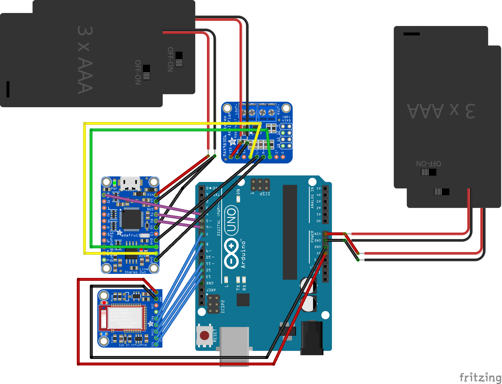
I'm trying to figure out how to trigger this with the arduino, whether it be connecting a trigger pin on the sound board to ground or via serial interface. I need to be able to trigger audio without a connection to the computer, so I'm thinking that I can't use the serial interface. Yet at the same time, I need the arduino itself to trigger the sound, so I'm not sure how to best do this. From what I have gathered, I can set a pin to ground, but it can only take about 20 mA. I'm currently powering that board with 3 AA batteries. see attached. I can also use the 5v or 3.3 v output if need be.
The walkthrough demonstrates using an actual switch to connect a trigger pin to ground and thus trigger an audio file. I'm looking to do this without the need for an actual person to press a switch- can I selectively connect a trigger pin to ground purely through arduino and software?
You can apply the same principle; put a diode between the Arduino pin and the board trigger pin; the board side has a pull-up resistor so will be pulled to 3.3V. If the Arduino provides a high signal, the diode will block and no 5V will reach the processor on your audio board and the processor will see 3.3V (high) as the diode blocks. If the Arduino provides a low signal, the diode will conduct and the processor on your audio board will see the voltage drop over the diode (approx. 0.6V for an 1N4148) which the processor on the audio board will interpret as low (max. low level input voltage is specified as 0.3 * IOVDD).
Make sure you put the diode the right way.
// Edit
You mentioned 20mA in the opening post. You're not switching the power of the board for triggering, your switching the trigger pins. Your audio board has 100 kOhm pull-up resistors so the max. current that will flow through the Arduino pin is 3.3V/100k = 33 uA (far lower than the maximum that an Arduino pin can handle).