Hi all!
I am just wondering if there are any best practices available for getting ready an Arduino project.
I am quite sure I am using the wrong keywords in my search. Maybe you can point me into the correct direction?
At the moment I have three boards connected with several cables and everything looks a bit messy. But hurray it is alive and ready to go live.
I am thinking about soldering everything to a breadboard and replace the prototyping board. Furthermore I would glue everything into a water proofed box.
But it would not surprise me you have 10 more ideas how to go ahead. What about power e.g.? Anything I should keep in mind for a 24h usage?
Thanks in advance! Looking forward to benefit from your experience.
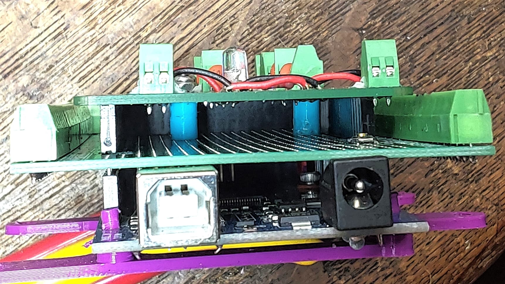
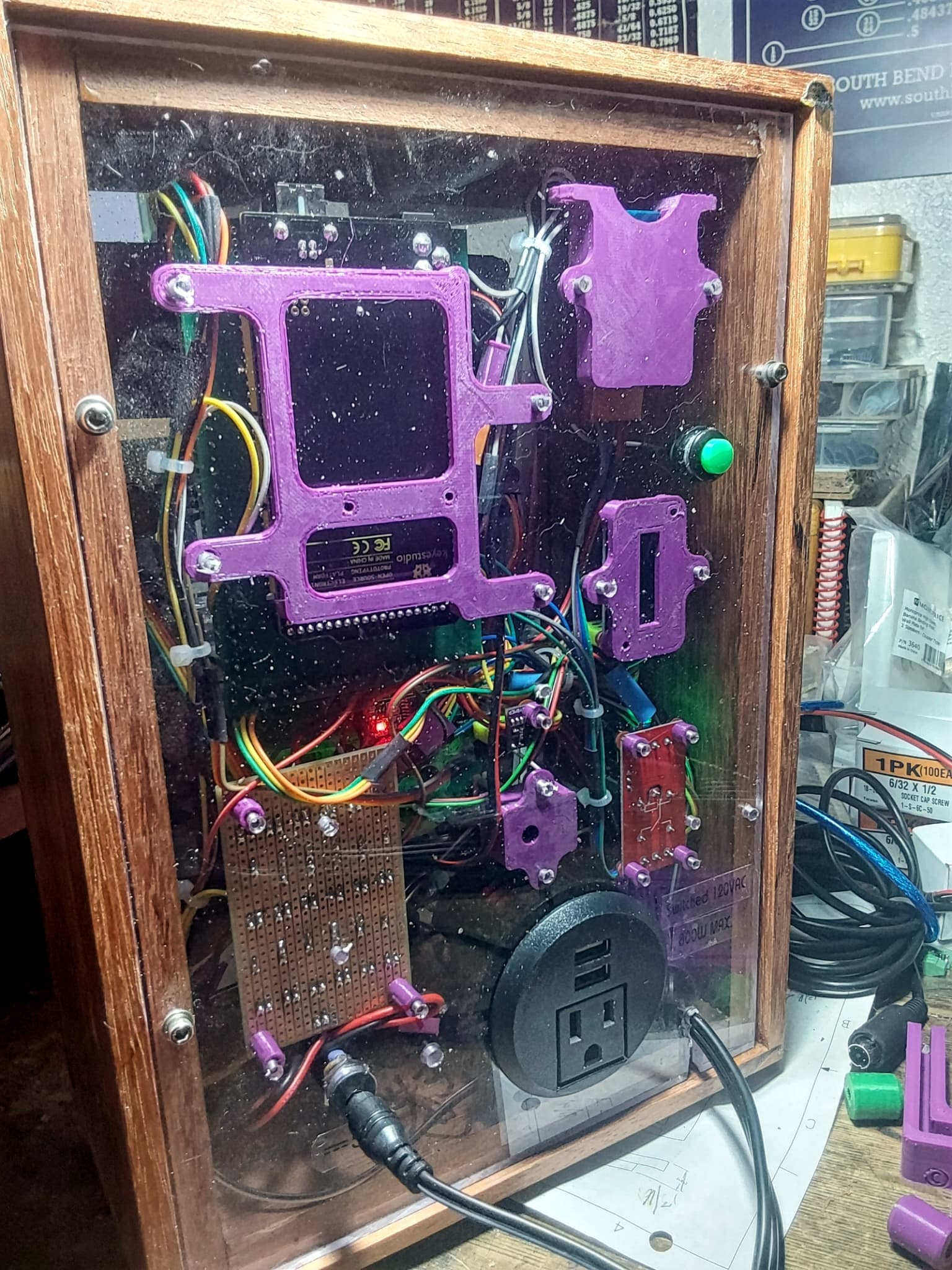
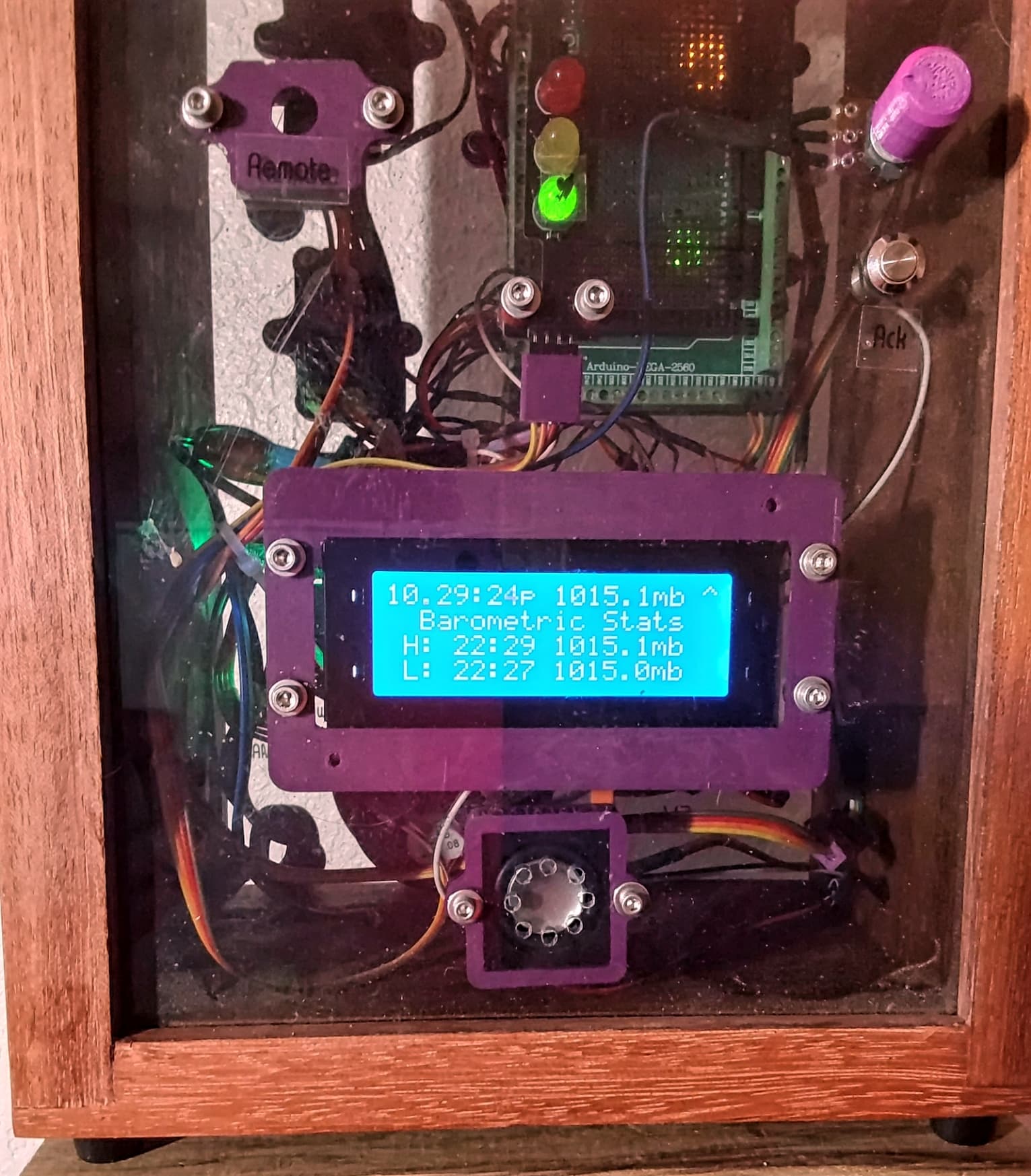
I think the very first thing to do is to develop a schematic. Draw it by hand or use a CAD program. A real schematic, not a diagram like a Fritzing breadboard. Those leave out too much information.
The PDB is fed clean +5 from a quality (medical grade, worldwide approvals) "wall wart" and feeds everything else clean power with local bypass to reduce cross coupling.
I buy Mega 2560 clones at Walmart for under $20. The screw terminal shield is under $15 as a kit or under $20 assembled. The PDB takes 1/2 to make and under $15 parts. Total outlay $55 and ready to mount. The ps is another $20.
This gives 70 IO points for around $1 each, ready to wire.
I add 3D printed shrouds on the duponts to gang them and makes it lots easier to insert/remove, but also aides in retention, gives a place to label, id's pin #1 and allows color coding.
I build on 1/4" lexan. It drills and taps easily and comes in clear or colors.
Hi all!
Thanks for your several comments and replys.
Yes this was a very unspecific question. This is why I am not mentioning any details.
My question should match to any kind of project.
I now ordered a waterproofed electronic box and cable pass adapters. Furthermore, I will replace my prototyping board with a well-solered installation. In the end, everything will be glued in place.
PS: I really like the 3d printed solution. But this will be like a new box of pandora for me. Maybe next year