Hi everyone,
I'm facing troubles with the audio peripherals on GIGA R1 Wifi board.
I am trying to use it to develop a multichannel audio processing algorithm (2 channels in, N channels out).
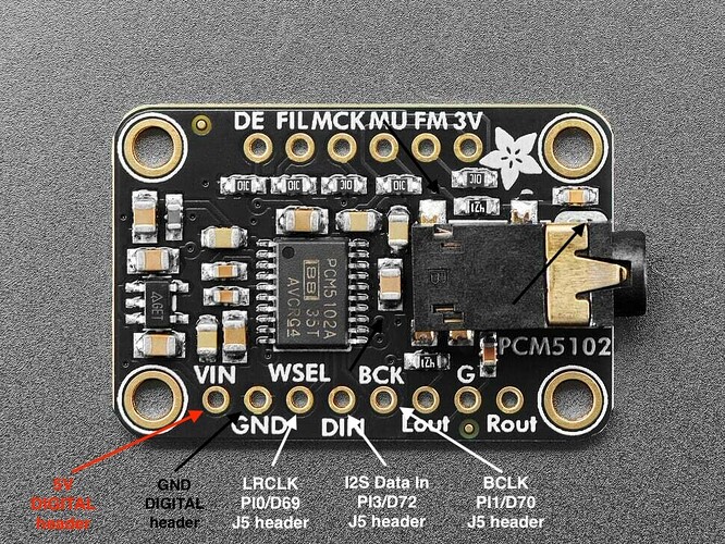
I bought this chip from Adafruit as an external DAC output driven by GIGA R1 I2S outputs:
I'm using the following pins from the GIGA R1 board for the I2S output (J5 header):
- LRCLK: PI0
- BCLK: PI1
- DIN: PI3
I am using Arduino_AdvancedAnalog library to drive the I2S external DAC, the internal ADC and the internal DAC.
It works if I feed the I2S signal with a sinewave generated at runtime or with samples from a wav file on a USB stick (using the I2S_DAC_Output.ino example from Arduino_AdvancedAnalog library).
Nevertheless I did not succeed in getting a clean audio input from GIGA internal ADC (pins A0/A1) and feed the signal to this external DAC.
I can hear the input signal but I get a huge distorded noise on top of it by listening to the sound from the PCM5100.
It works if I use the internal 12 bits DAC (pins A12/A13) though.
Here is my current test code:
#include <Arduino_AdvancedAnalog.h>

#define SAMPLE_RATE 48000
#define FRAME_SIZE  256
#define NB_BUFFERS  32

#define I2S
#define DAC

uint32_t frame_counter = 0;

#define DAC_RESOLUTION AN_RESOLUTION_12
#define DAC_MAX_VAL (256 * 2 << (DAC_RESOLUTION * 2))
#define ADC_RESOLUTION AN_RESOLUTION_16
#define ADC_MAX_VAL (256 * 2 << (ADC_RESOLUTION * 2))

AdvancedADC adc1(A0);
AdvancedADC adc2(A1);
#ifdef DAC
AdvancedDAC dac1(A12);
AdvancedDAC dac2(A13);
#endif

#ifdef I2S
// WS, CK, SDI, SDO, MCK
AdvancedI2S i2s(PI_0, PI_1, NC, PI_3, NC);
#endif

void setup()
{
  Serial.begin(115200);
  while (!Serial);

  // ADC init
  Serial.println("Initialize ADC");
  if (!adc1.begin(ADC_RESOLUTION, SAMPLE_RATE, FRAME_SIZE, NB_BUFFERS)) {
      Serial.println("Failed to start ADC1!");
      while (1);
  }
  if (!adc2.begin(ADC_RESOLUTION, SAMPLE_RATE, FRAME_SIZE, NB_BUFFERS)) {
      Serial.println("Failed to start ADC2!");
      while (1);
  }
#ifdef DAC
  // DAC init
  Serial.println("Initialize DAC");
  if (!dac1.begin(DAC_RESOLUTION, SAMPLE_RATE, FRAME_SIZE, NB_BUFFERS)) {
      Serial.println("Failed to start DAC1!");
      while (1);
  }
  if (!dac2.begin(DAC_RESOLUTION, SAMPLE_RATE, FRAME_SIZE, NB_BUFFERS)) {
      Serial.println("Failed to start DAC2!");
      while (1);
  }
#endif
#ifdef I2S
  // I2S init
  Serial.println("Initialize I2S");
  if (!i2s.begin(AN_I2S_MODE_OUT, SAMPLE_RATE, FRAME_SIZE, 32)) {
      Serial.println("Failed to start I2S");
      while (1);
  }
#endif
}

void loop()
{
  bool out_available = true;

#ifdef I2S
  out_available = out_available && i2s.available();
#endif
#ifdef DAC
  out_available = out_available && dac1.available() && dac2.available();
#endif

  if(out_available && adc1.available() && adc2.available())
  {
    Serial.println("Frame " + String(frame_counter));
    //Serial.println(adc_input_buf[0]);
    //Serial.println(adc_input_buf.size());

    SampleBuffer inBuff1 = adc1.read();
    SampleBuffer inBuff2 = adc2.read();
#ifdef DAC
    SampleBuffer outBuff1 = dac1.dequeue();
    SampleBuffer outBuff2 = dac2.dequeue();
#endif
#ifdef I2S
    SampleBuffer txbuf = i2s.dequeue();
#endif

    for (size_t i=0; i<FRAME_SIZE; i++)
    {
#ifdef DAC
      outBuff1.data()[i] = map(inBuff1[i], 0, ADC_MAX_VAL - 1, -DAC_MAX_VAL / 2, DAC_MAX_VAL / 2 - 1);
      outBuff2.data()[i] = map(inBuff2[i], 0, ADC_MAX_VAL - 1, -DAC_MAX_VAL / 2, DAC_MAX_VAL / 2 - 1);
#endif
#ifdef I2S
      txbuf[2 * i] = (int16_t)map(inBuff1[i], 0, ADC_MAX_VAL - 1, -32768, 32767);     // L
      txbuf[2 * i + 1] = (int16_t)map(inBuff2[i], 0, ADC_MAX_VAL - 1, -32768, 32767); // R
#endif
    }

#ifdef DAC
    // Write contents of the output buffer to the DACs
    dac1.write(outBuff1);
    dac2.write(outBuff2);
#endif
#ifdef I2S
    // Write to i2s output buffer
    i2s.write(txbuf);
#endif

    // Release the input buffers
    inBuff1.release();
    inBuff2.release();

    frame_counter++;
  }
}
To replicate the issue, I just comment/uncomment those 2 define to disable/enable I2S or internal DAC:
#define I2S
#define DAC
Does anyone get any clue why I get this behavior?
Is it because the Advanced Analog library fails at synchronising the ADC/DAC and I2S DMA buffers?
Thanks for your help ![]()


