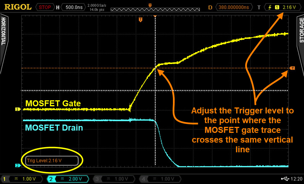
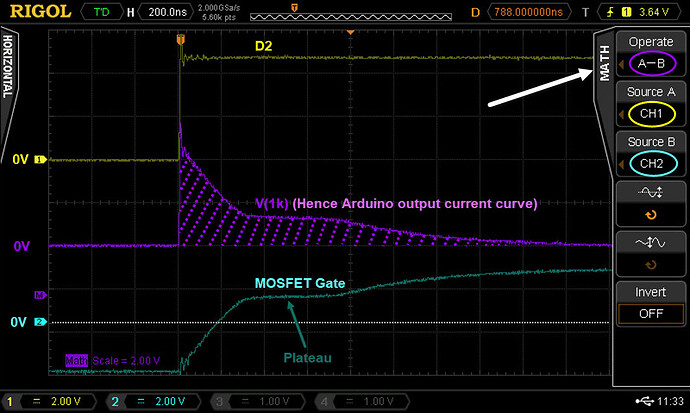
At the falling knee of the pink display, what is the voltage on the gate (yellow) ?
It says 22.40V. ![]()


Suggestions for the TDR:
-
get a known length of 50 ohm coax
-
and another known length of 50 ohm coax
-
and a known length of 75 ohm cable TV coax
-
and a 50 ohm load
-
and a 75 ohm load
-
and a short
-
use the TDR to determine the pulse length of each coax and calculate the scope trace to coax length ratio
-
put the 50 ohm cables end to end with the far end terminated and find the middle connector
-
put a 50 ohm coax, a 75 ohm coax, and the other 50 ohm coax together and see the fine mess that creates
-
repeat all experiments with all possible combinations of 50 ohm, 75 ohm, open, and short circuit terminations
put a length of unterminated coax in the TDR and cut it close to the end while watching the TDR trace
Not pulling your leg: in the days of way back when they would hang a length of coax in a vertical borehole for a nuclear bomb test and measure the speed of the shockwave by filming a TDR as the RG213 turned into RG174
To be fair most oscilloscopes I see these days has a TV trigger option, this is a frame sync trigger, and the normal trigger can be used as a line sync trigger.
At one time I even used a scope that would allow you to set the actual line number of the line sync pulse to trigger on. Although a time delayed trigger will let you sort of do that.
I think the problem these days is finding a composite video signal to look at. They used to be common but now are not so common.
Which is why the form 0μ1 was invented, no mistaking where the decimal point goes.
Bonus Hint.
- Measure a voltage on a frozen trace without cursors.
We want to measure the voltage of the point in a MOSFET gate trace at the point the MOSFET first turns on.
Edit
- And obviously, if you want to measure voltage points on the MOSFET Drain (blue trace), you will need to trigger on that trace first.

Sorry, @LarryD. Iv'e been so busy lately. Ill figure out your quiz soon ![]() .
.
Going to have to change the way I do things.
![]()


Yes, why is it so slow? Is that just the Arduino? Oh, if I use a signal generator, there would be a faster rise time on the pulses, right?
Well it is not the Arduino's rise time. It is the fact that it can't supply enough current to charge the gate capacitance fast enough. That is why FETs are often used with FET drivers. These supply enough current to turn on the FET faster.
It depends on the output impedance of the signal generator, so it will not necessary be faster.
Oh. That makes sense! Thanks @Grumpy_Mike ! Still learning here ![]() .
.
I think we all are. Nobody knows everything.
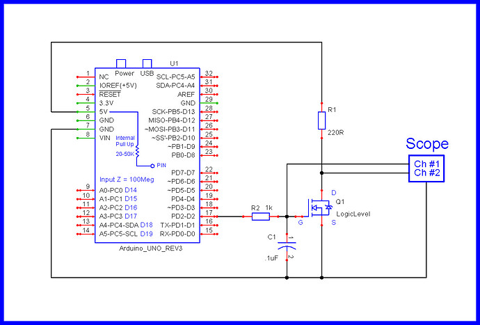
And, If we are talking about this schematic.
I purposely had you add a 0.1uF ( 0μ1) capacitor to slow down the voltage of the gate rise.
I wanted you to see a slow slope on both the gate and drain.
In a real circuit, however, we would never add a capacitor to the gate like this as the MOSFET would switch too slowly, hence consume power and generate heat.
Seen here, the gate is switching very ssllooww therefore we have slowed down the drain.

In post #104.
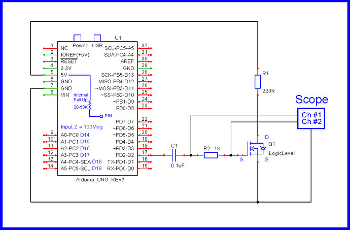
Notice in this instance, the gate is switched through a capacitor.
As a result, the gate voltage (blue trace) goes from a negative to positive voltage.
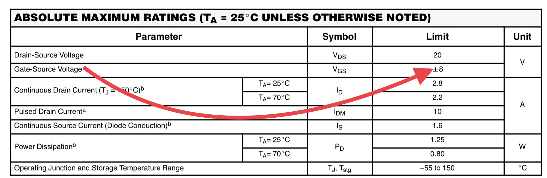
When you look at a MOSFET data sheet, we see ± on the maximum gate rating.
I wanted you to see that a negative voltage could be applied to the gate.