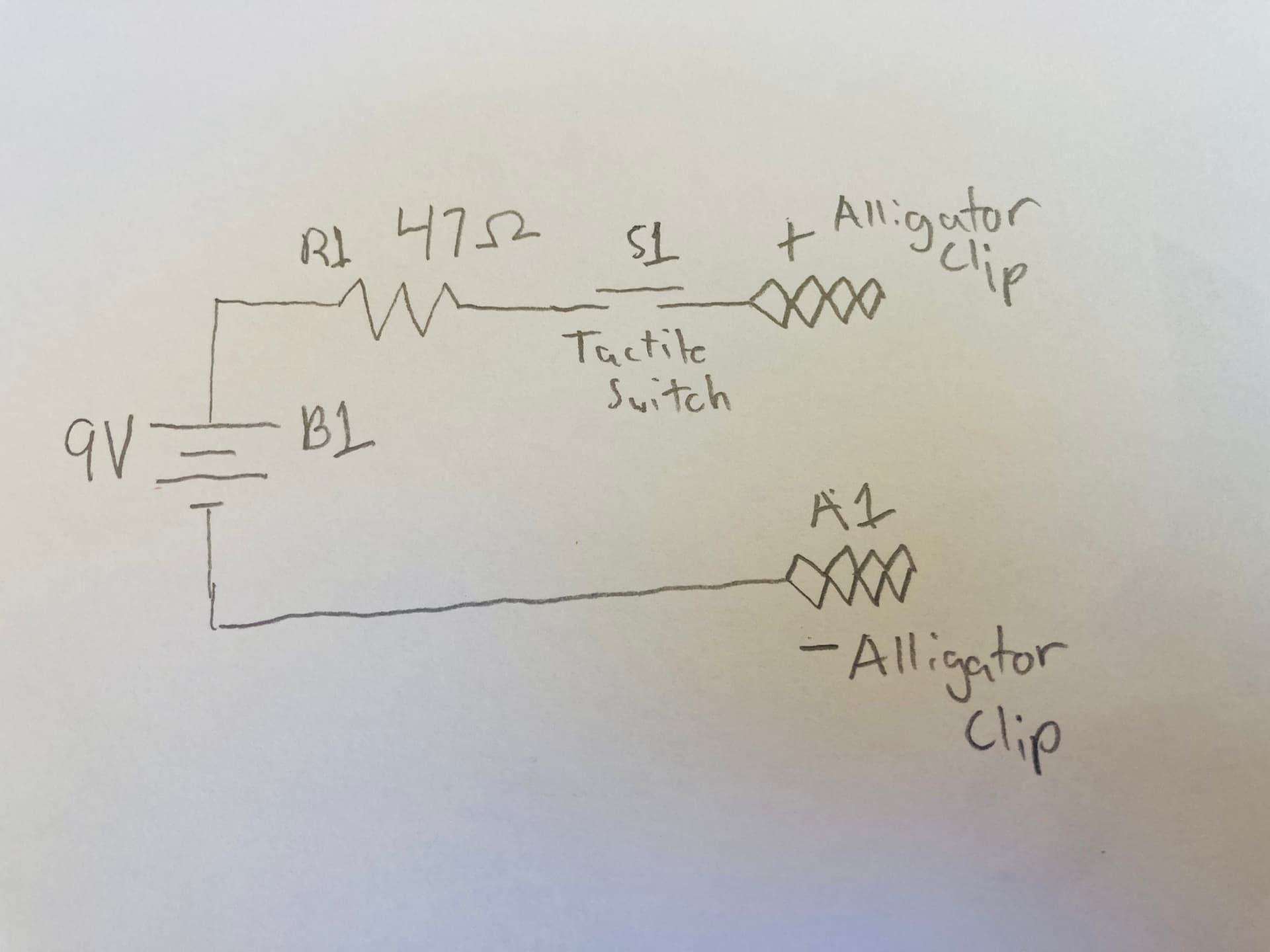
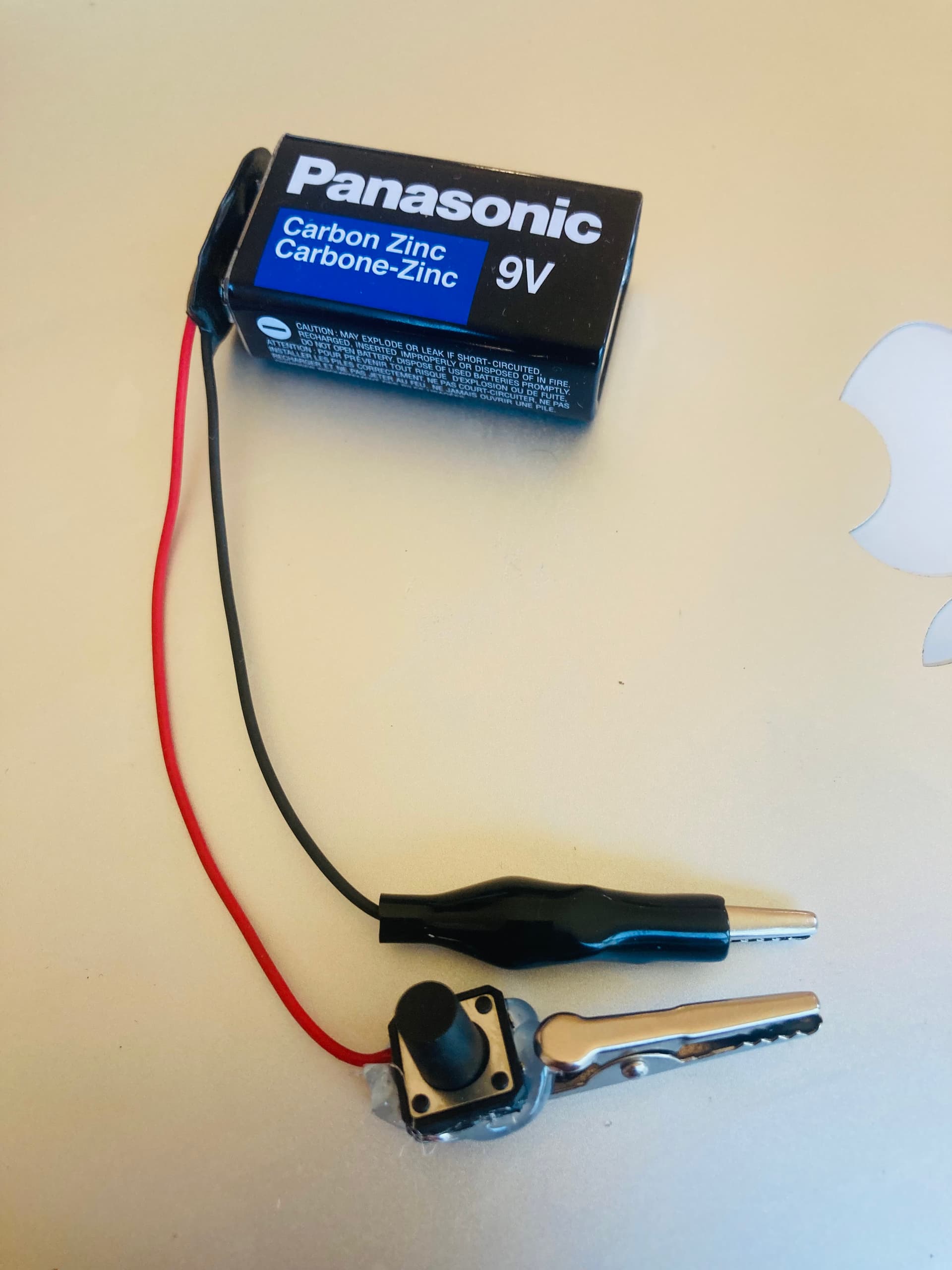
The unknown wire in this example is a medium length extension cord.
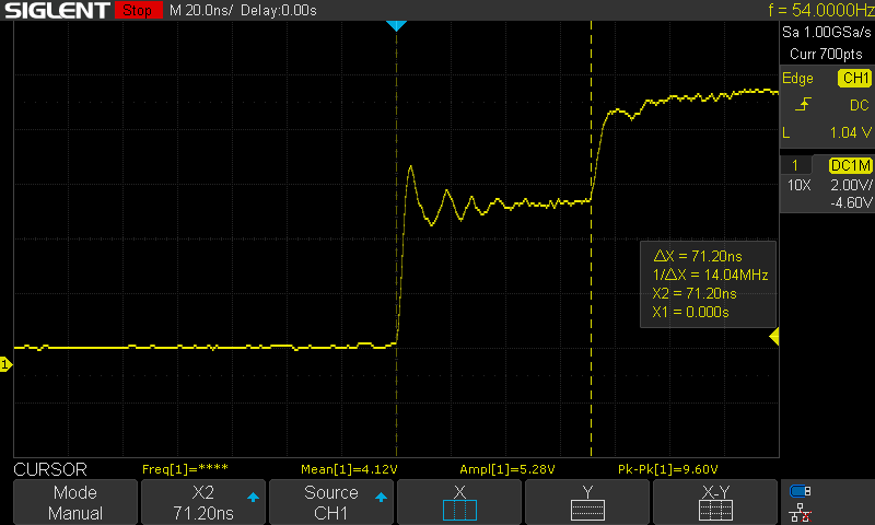
You then use the Cursors to measure the time difference between the bottom of the first spike, and the bottom of the second spike.
Once you have your measurement (71.20ns in this example), use this calculation to get the distance in feet:
(71.20ns * 0.983 * 0.67) / 2 = 23.44 feet
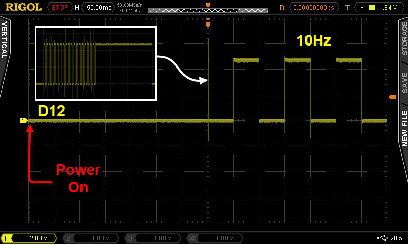
When starting a millis( ) based TIMER you must reset it !
One way to Corrected sketch:
const byte clockLED             = 12;

bool greetingFlag               = false;

unsigned long clockMillis;

const unsigned long interval    = 50;  //50ms

//*********************************************************************************
void setup()
{
  Serial.begin(9600);

  pinMode(clockLED, OUTPUT);

} //END of   setup()


//*********************************************************************************
void loop()
{
  //******************************************
  //at the begining of the sketch print a greeting
  if (greetingFlag == false)
  {
    //print a greeting to the user
    Serial.println("Welcome to Oscilloscope Training.");

    //give 2 seconds to read the serial monitor
    delay(2000);

    //we have finished with the greeting, disable it form here on in
    greetingFlag = true;

    //start the TIMER
    clockMillis = millis();        //  <------<<<<<<   reset the TIMER
  }

  //******************************************
  //toggle the clock LED every 50ms
  if (millis() - clockMillis >= interval)
  {
    //restart the TIMER
    clockMillis = clockMillis + interval;

    //toggle LED
    digitalWrite(clockLED, !digitalRead(clockLED));
  }

} //END of loop()
const byte clockLED             = 12;

bool greetingFlag               = false;

unsigned long clockMillis;

const unsigned long interval    = 50;  //50ms

//*********************************************************************************
void setup()
{
  Serial.begin(9600);

  pinMode(clockLED, OUTPUT);

} //END of   setup()


//*********************************************************************************
void loop()
{
  //******************************************
  //at the begining of the sketch print a greeting
  if (greetingFlag == false)
  {
    //print a greeting to the user
    Serial.println("Welcome to Oscilloscope Training.");

    //give 2 seconds to read the serial monitor
    delay(2000);

    //we have finished with the greeting, disable it form here on in
    greetingFlag = true;

  }

  //******************************************
  //toggle the clock LED every 50ms
  if (millis() - clockMillis >= interval)
  {
    //synchronize the TIMER if there are delays in the code   <------<<<<<<
    while (millis() - clockMillis >= interval)
    {
      clockMillis = clockMillis + interval;
    }

    //toggle LED
    digitalWrite(clockLED, !digitalRead(clockLED));
  }

} //END of loop()
This is the method I use 99% of the time, see the <--------<<<<< line of code:
const byte clockLED             = 12;

bool greetingFlag               = false;

unsigned long clockMillis;

const unsigned long interval    = 50;  //50ms

//*********************************************************************************
void setup()
{
  Serial.begin(9600);

  pinMode(clockLED, OUTPUT);

} //END of   setup()


//*********************************************************************************
void loop()
{
  //******************************************
  //at the begining of the sketch print a greeting
  if (greetingFlag == false)
  {
    //print a greeting to the user
    Serial.println("Welcome to Oscilloscope Training.");

    //give 2 seconds to read the serial monitor
    delay(2000);

    //we have finished with the greeting, disable it form here on in
    greetingFlag = true;

  }

  //******************************************
  //toggle the clock LED every 50ms
  if (millis() - clockMillis >= interval)
  {
    //if some inaccuracy can be accepted use this      <------<<<<<<
    clockMillis = millis();

    //toggle LED
    digitalWrite(clockLED, !digitalRead(clockLED));
  }

} //END of loop()