GPIO capacitive load test

I've noticed that the effect of capacitively loading an Arduino GPIO is a perennial question, that tends to attract speculative argument. It's not surprising we resort to anecdote and superstition, given the lack of firm guidance from Atmel. I became interested in the same question recently, and being of the empirically motivated type, thought I'd chuck two data points into the sea of possibility.

I picked two Arduino UNO, new out of the box, to sacrifice at the alter of experimentation. One is a genuine R3 and one a R3 clone from DuinoTECH. I have no reason to expect a difference between the two, given that an ATmega328P is an ATmega328P, but it doesn't hurt to broaden the sample space a little.

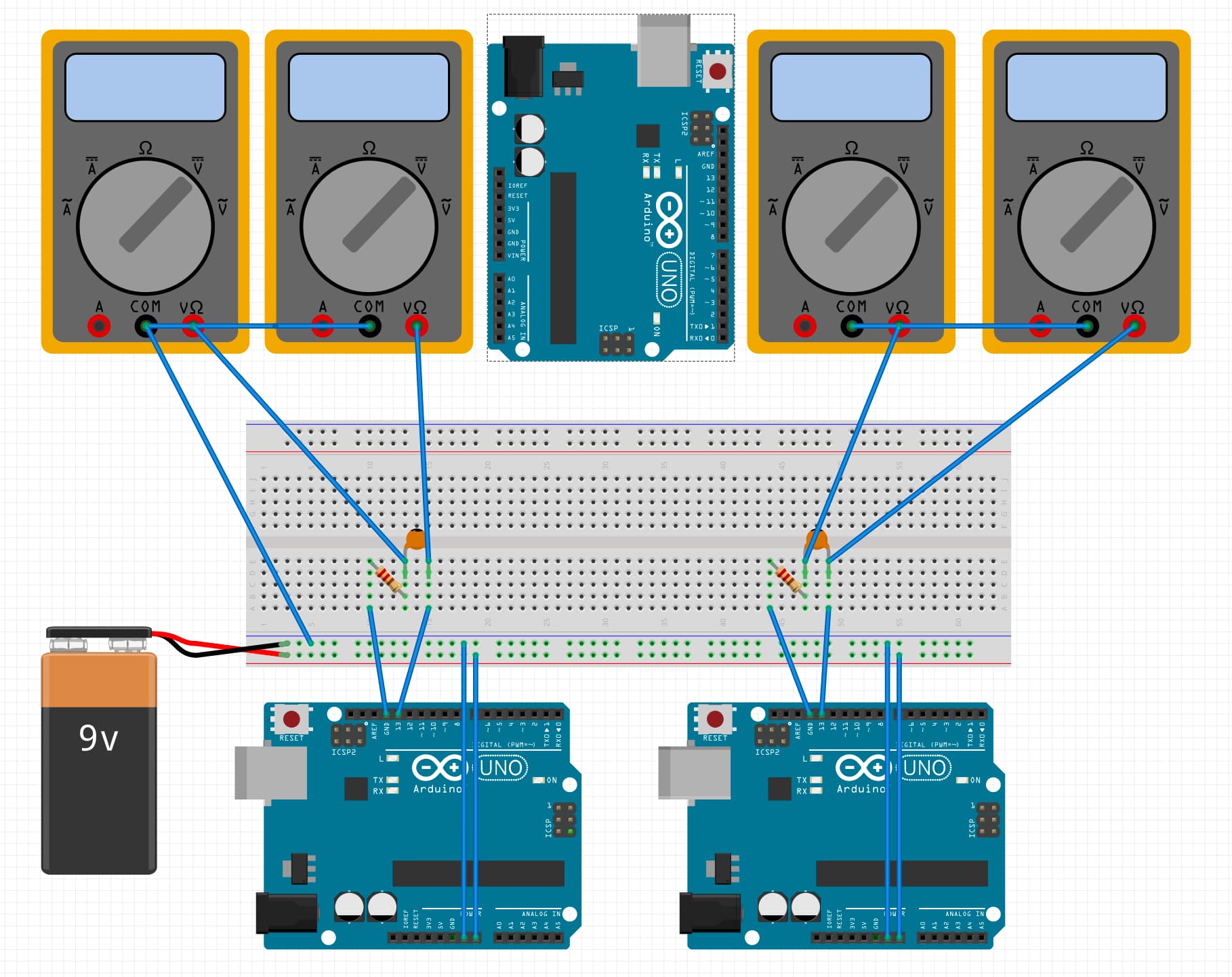
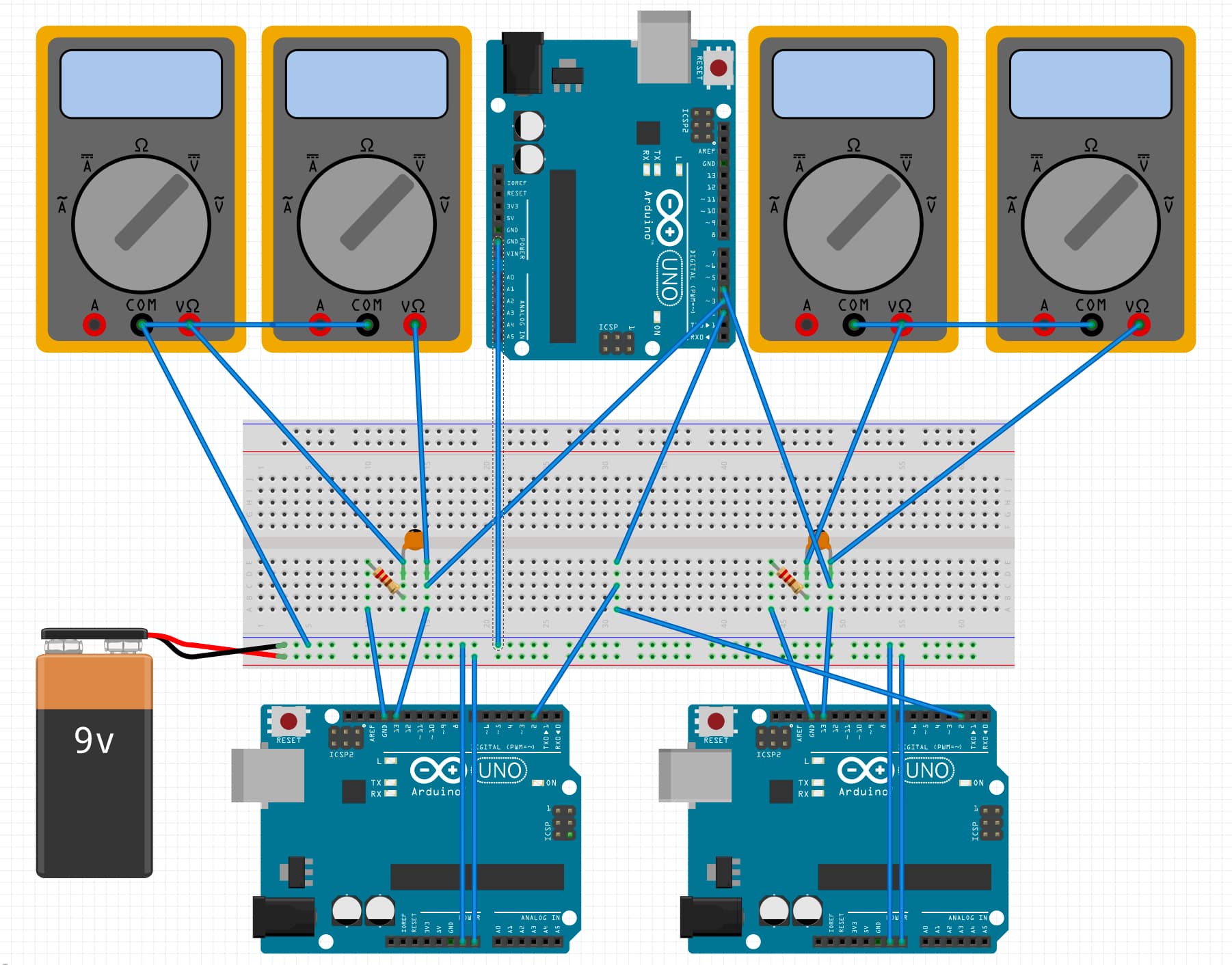
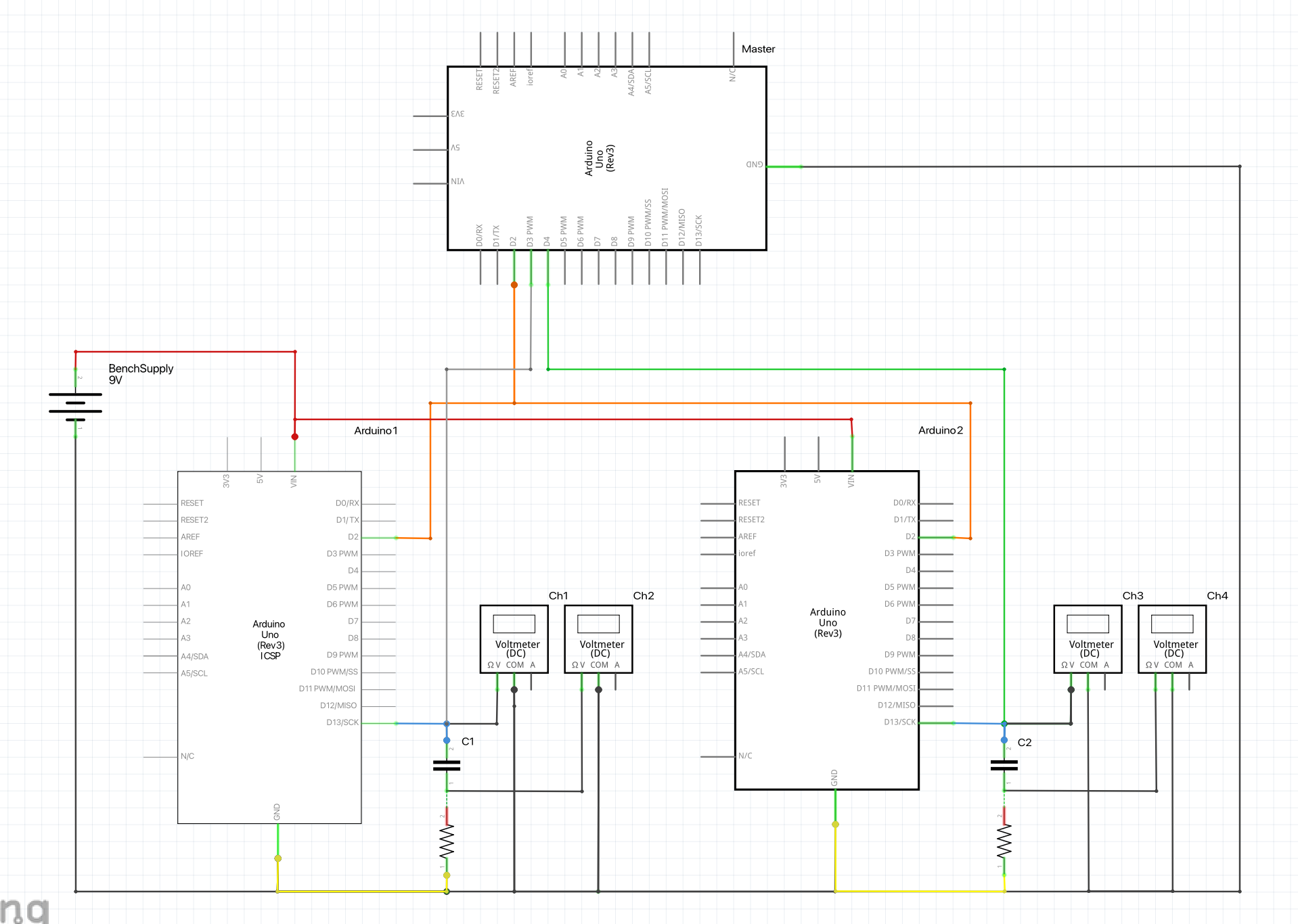
Both Arduinos are connected to their own resistor and capacitor in series, between GPIO pin D13 (blue wires) and ground (yellow wires). The resistor is on the ground side and the capacitor is on the GPIO side. Both Arduinos monitor their GPIO pin D2 (orange wires), which is periodically toggled by another UNO acting as master. When the slave Arduinos detect a change, they mimic it on D13. The master meanwhile, monitors the two slave D13 pins (white and green wires) to check when the signal has been faithfully propagated.

Both Arduinos are powered by a bench supply set to 9V (red and black wires). All three Arduinos share a common ground, which is not shown in the photo.

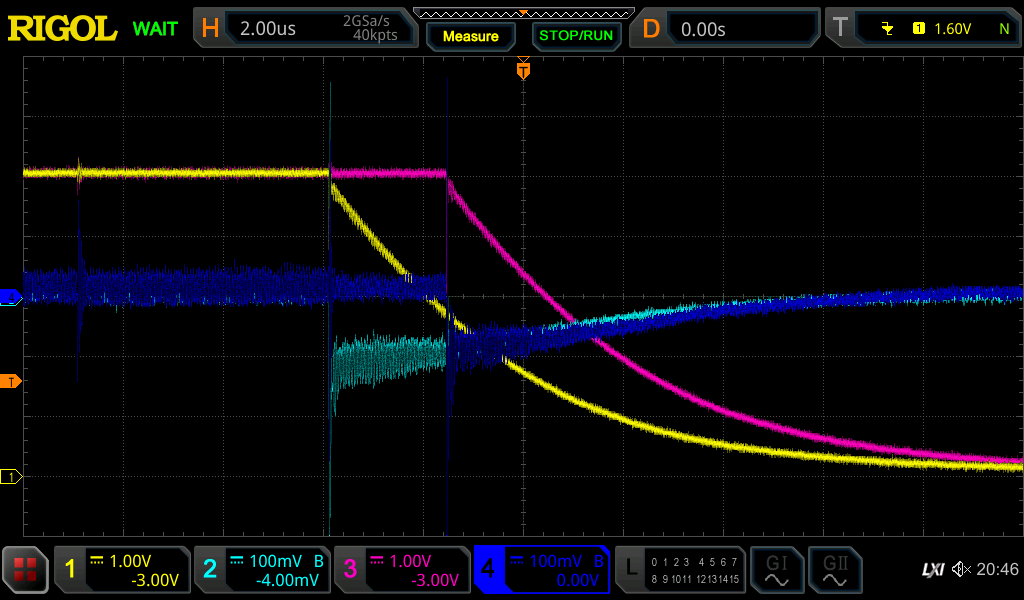
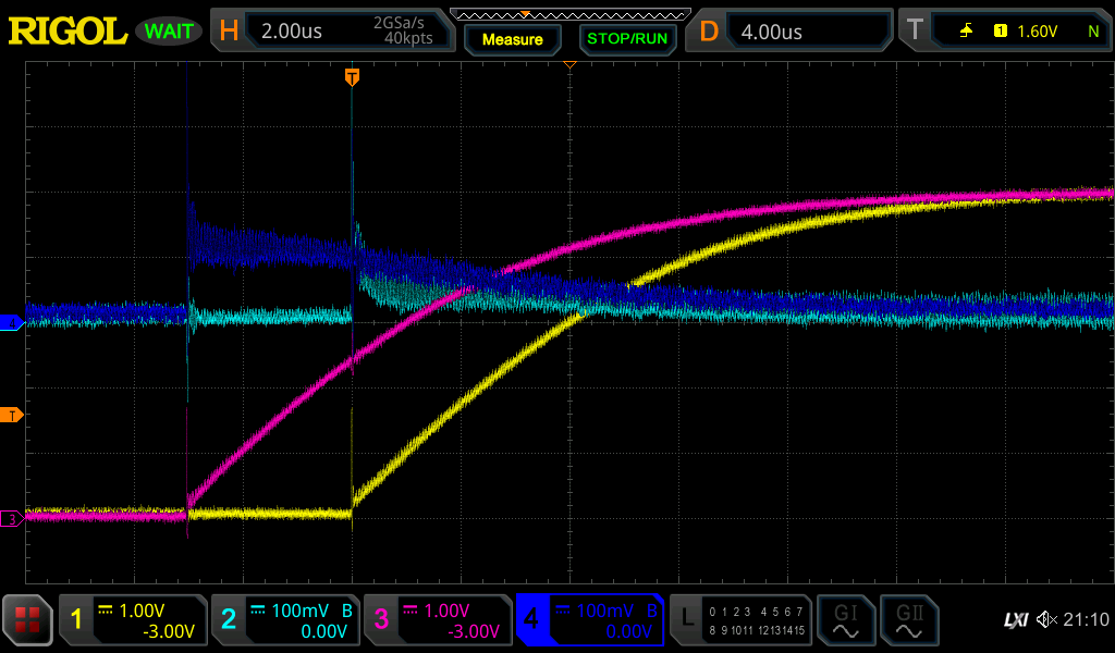
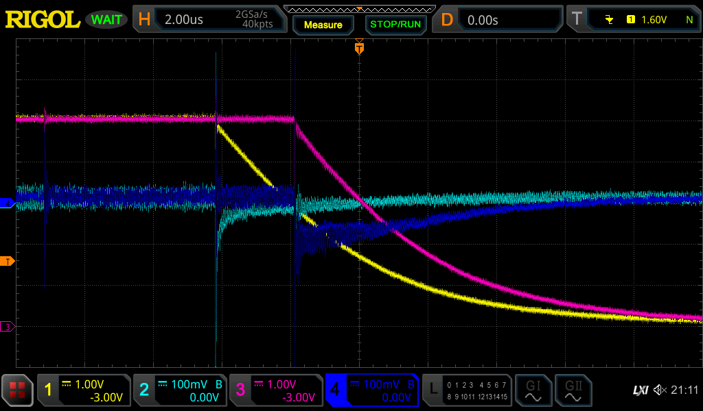
With a CRO I'm measuring:

  • Channel 1 and 3: voltage at D13, with respect to ground. Hereafter, the "pin voltage".
  • Channel 2 and 4: voltage between cap and resistor, with respect to ground. Hereafter, the "voltage across the resistor".

Everything is as long leaded and crudely breadboarded as you can see.

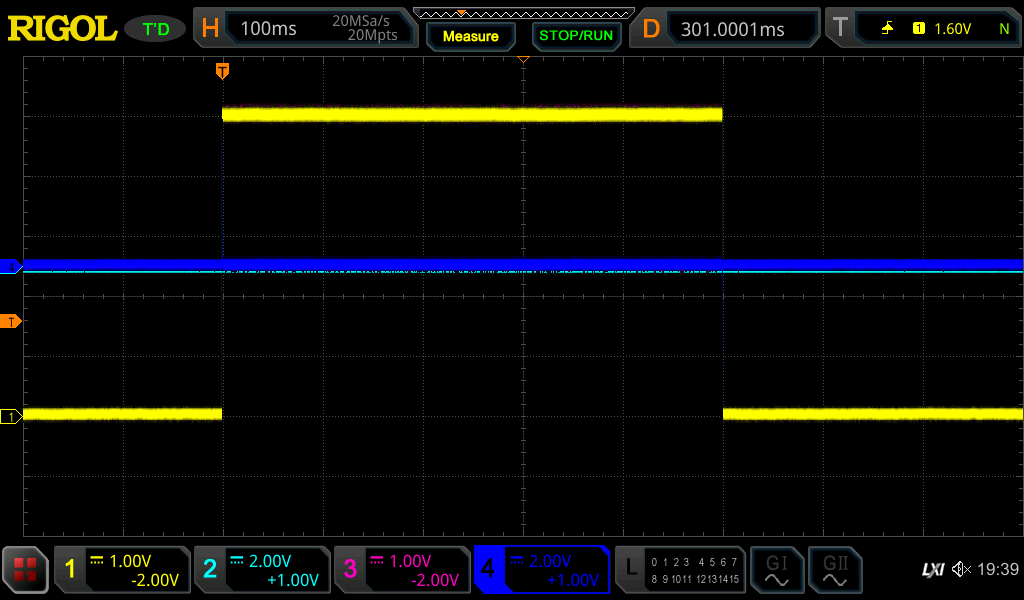
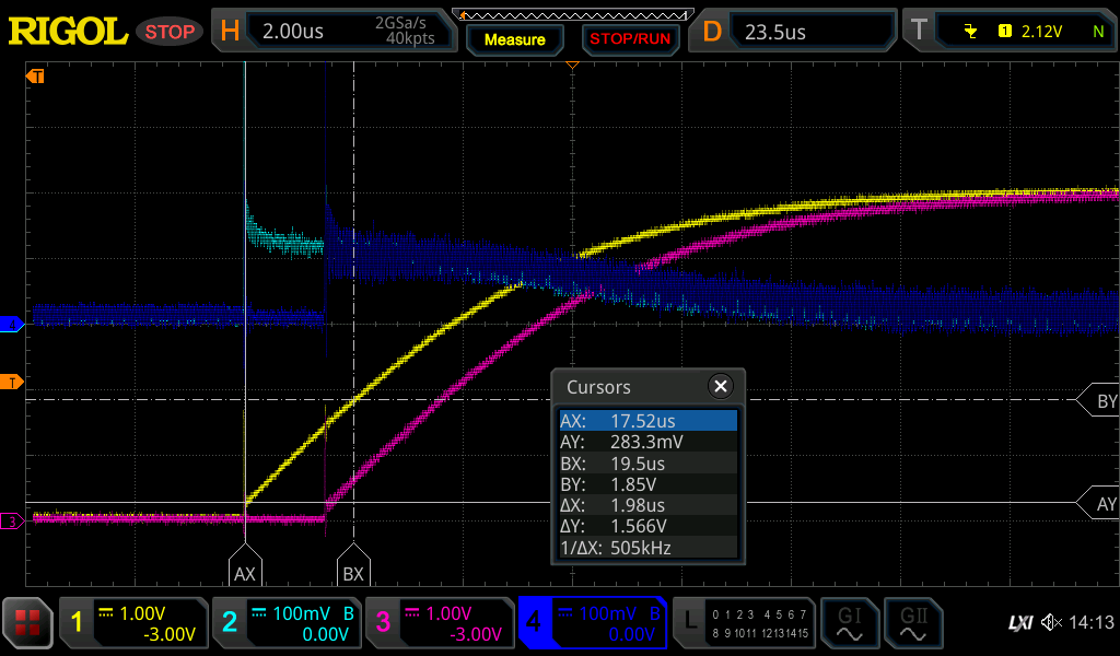
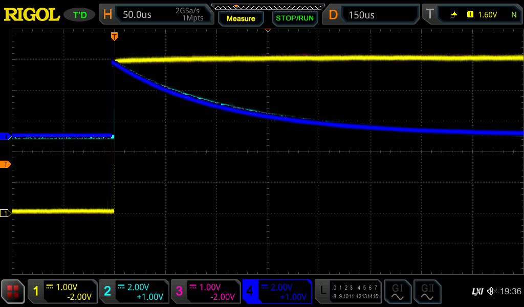
I warmed up with a 1kΩ 1% 0.5W and a 0.1µF 20% 50V Y5V ceramic capacitor, and a pulse period of 1 second.

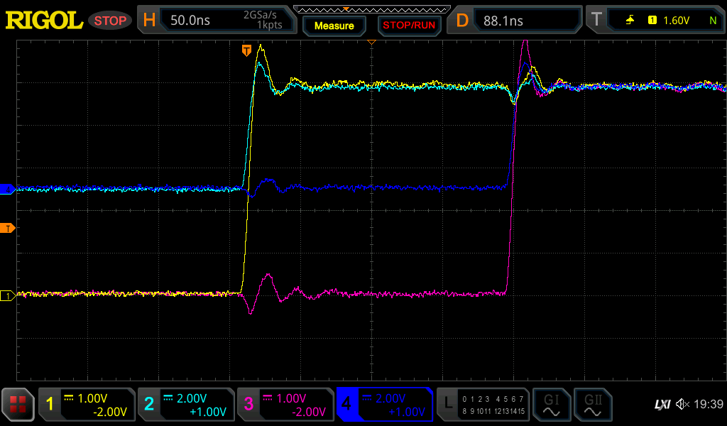
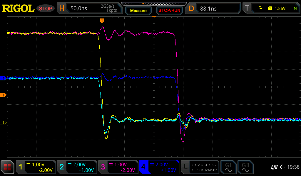
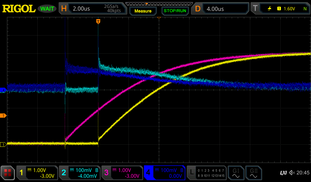
The rising and falling edges are as you would expect - the GPIO pin manages nearly the full 5V swing, only having to source or sink 5mA, and decaying to full voltage and zero current with a time constant of about 100µs. There is some very minor discrepancies between Arduino 1 and 2, as you might expect from component tolerances and the variance in response time to the master signal.

... splitting into multiple posts because I'm an untrusted noob ...

Zooming in on the transition shows a sharp rise/fall time in the order of 10ns, and as much ringing and coupling as you might expect from the bird's nest wiring. The arbitrary response time of each Arduino is clear at this scale.

And for completion sake, a complete cycle. At this scale, the current waveform, voltage transitions and Arduino discrepancies are barely perceptible.


Time to move on to the first skirmish: the same 0.1µF cap and 1 second pulse period, but dropping the resistance to 1Ω. In fact, the resistor is only there to get some semblance of a current measurement. With the assumption of a couple of tens of ohms of source resistance in the Arduino, this scenario is intended to be representative of a purely capacitive load. Validation of that intention is included below.

Rising and falling waveforms:

Suddenly we have a lot going on. The transition is now significantly current limited, as evidenced by the gradual pin voltage change. The voltage across the resistor is very noisy at this scale, but seems to indicate a very big, very short spike, followed by a decay from about 120mA to zero over 12µs or so. By taking a few measurements of the voltage change in the first 1 or 2 microseconds, linearising and applying $i=C*dV/dt$, the current after the spike is likely to actually be no more than about 80mA. This figure is easily ±20% given all the sources of error, although the capacitors measure as within -1%, and other calculation methods arrive at very similar values. Further, shorting out the resistor to confirm it has negligible effect (see below) also suggests both the spike and the 40mA discrepancy between measurement and calculation can be explained by coupled noise. I have a current meter I could verify with, but at this stage the confidence in the measurements is more than sufficient for the purpose of this test.

I tried zooming in on the transition, but the signals are so dominated by noise at that scale that they're largely useless.

To confirm the resistor has negligible effect on behaviour, I shorted out Arduino 1's resistor with a jumper wire. The rising and falling results are below:

The rise/fall times of the pin voltage are barely affected, in accordance with the assumption. Interesting though, significant voltage is still measured across the resistor. This suggests that the initial spike and up to 40mA or so measured thereafter is purely due to noise, not due to current through the resistor. This is not surprising, given the small signal and the measurement setup, and aligns with the calculations of actual current mentioned above.

What is clear, is that the 40mA absolute maximum current specification of the ATmega328P is being exceeded for at least 4µs on each transition.

However, cycle by cycle the RMS of the current is practically zero. The cycle waveforms are shown below. The greater resistor noise during the high state is interesting, but easily explained and beside the point here. Otherwise, it's unremarkable.

So the question now is, is this causing damage? We can never been certain from this test, but I've left it running for about 2 hours now. So far, both Arduinos have completed 5400 transitions from low to high and 5400 transitions from high to low, and there are no signs of degraded performance.

I'll leave this running as long as I can reasonably manage, and let you know what I find.

Appendix: Source Code

slave.ino

#define PIN_PUT 13 //Pin Under Test
#define PIN_MASTER 2

void setup() {
  pinMode(PIN_PUT, OUTPUT);
  pinMode(PIN_MASTER, INPUT);
}

void loop() {
  digitalWrite(PIN_PUT, digitalRead(PIN_MASTER));
}

master.ino

#define PIN_OUTPUT 2
#define PIN_INPUT1 3
#define PIN_INPUT2 4
#define PERIOD_MS 1000

void setup() {
  pinMode(PIN_OUTPUT, OUTPUT);
  pinMode(PIN_INPUT1, INPUT);
  pinMode(PIN_INPUT2, INPUT);

  Serial.begin(9600);
  Serial.println("Master starting.");
}

void loop() {
  static unsigned long numOutput = 0;
  static unsigned long numInput[2][2] = {0}; //indexed by input then by level
  
  //For levels low then high
  for(int level = 0; level < 2; level++)
  {
    int value = level ? HIGH : LOW;
    digitalWrite(PIN_OUTPUT, value);
    delay(PERIOD_MS/2);

    // For inputs 1 then 2
    for(int input = 0; input < 2; input++)
    {
      //Make sure the input eventually reached the output
      if(digitalRead(input ? PIN_INPUT2 : PIN_INPUT1) == value)
        numInput[input][level]++;
      else
      {
        Serial.print("*** Missed ");
        Serial.print(level ? "high " : "low ");
        Serial.print(input ? "2 " : "1 ");
        Serial.println("***");
      }
    }
  }

  if(++numOutput % (30l*60*1000/PERIOD_MS) == 0) //every half hour
  {
    Serial.print("numOutput[");
    Serial.print(numOutput);
    Serial.print("] numHigh1[");
    Serial.print(numInput[0][1]);
    Serial.print("] numHigh2[");
    Serial.print(numInput[1][1]);
    Serial.print("] numLow1[");
    Serial.print(numInput[0][0]);
    Serial.print("] numLow2[");
    Serial.print(numInput[1][0]);
    Serial.println("]");
  }
}

If degraded reliability is damage, then maybe.

Section 28.1
Exposure to absolute maximum rating conditions for extended periods may affect device reliability.

Section 29
The current drawn from capacitive loaded pins may be estimated (for one pin) as C L x VCC x f
where CL = load capacitance,
VCC = operating voltage and f = average switching frequency of I/O pin.

A circuit diagram were nice, with labels on the measurement points.

It looks more like you did not use a calibrated 1:10 probe?

It also were nice to have the colors labeled properly in the text WRT the circuit diagram.

A fuse can (should!) react on a single overload. The thin connectors inside a chip can show the same behavior, form hotspots, inject spikes, and other unwanted effects.

That's equivalent to value = level;

Yeah, a tough thing to prove either way. I certainly don't want people to extrapolate conclusions about reliability from this!

That's the one. And it's the "extended periods" bit that's hard to apply concretely. If it means 10ns, then Arduinos would be dropping like flies. If it means 10s then that's easy to work with. It's the grey area in between that includes transient behaviour, that leaves a bit of doubt.

Oh interesting! I missed that one. Funny, that works out to be the average current in one half cycle. So it's only including current in one direction, not the return, which I suppose makes a lot of sense given that it's in the section about current consumption. I was going to therefore dismiss it as not conservative enough for use in reliability calcs, but then it occurred to me that in the case of a GPIO, technically a large part of the sourcing circuit is separate to the sinking circuit, so perhaps it makes sense to only consider current in one direction at a time? It's still less conservative than an RMS calc, so I remain wary, but it's a handy estimate!

Oh yes, mea culpa. I overlooked that important step in my rush. Hopefully a Fritzing is clear enough.

First without the master circuit for simplicity, in pictorial form for reference.

Then with the master circuit.

And finally, the schematic.

I've tried to maintain the wire colour coordination, but it's come out a bit messy. Hopefully it is clear enough.

No, that's not it. 10x and cal'ed, and routinely put to use in more demanding scenarios.

Yeah, that's one of the few firm take-aways for me from this data - the absolute max definitely doesn't gaurantee 4µs fusing behaviour. Indeed, the source impedance restricts the maximum current to less than 3x the absolute max rating in this scenario, so we don't see any fast fuse effect.

Update from night one of operation:

  • ambient conditions ranged from 50% to 70% humidity and 18°C to 23°C.
  • 47000 transitions for each Arduino.
  • no perceptible difference in experimental behaviour.

There's a few directions I could take from here, but they quickly become less generally applicable. I could progressively ramp up the intensity to find the first point of conspicuous failure, but I'm not sure it would teach us much. Personally, I'd be happy to blindly assume caution is warranted, and once the RMS approaches the absolute max spec we're asking for trouble.

So, for the sake of one more comparative data point, I'm going to up the cycle rate from 1Hz to as fast as the delay() interface conveniently allows, and see what happens.

Well that was useful, but kinda boring. At 2ms per cycle, each Arduino completed 4,000,000 transitions without a single detected glitch or change in behaviour. Rise and fall times remain unchanged.

So I think I can rule out detecting a degradation using this method, due to cumulative effects. But even at 500Hz the actual transition barely occupies 2% of the cycle time, so I really haven't done anything to test sustained effects.

Feeling sufficiently nefarious today, I'm going to ratchet things up just a little further. If I decrease the period to about 50µs, then I should get a meaningful RMS cycle-to-cycle current. I'm expecting about 30-35mA RMS, which is about all the torture I'm willing to inflict for now.

I may be back with smoke to report.

Whee, that was fun. The closer I got to 50µs, the more I bumped into the limits of bit-banging and digitalRead. Nonetheless, I threw caution to the wind and got the waveform I wanted. Both Arduino's have just cracked 100 million transitions each, with a period of about 46µs. It's too fast to reliably check every transition with this setup, so I'm just monitoring the waveform with the oscilloscope.

See for yourself:

Not a whiff of any issues. The first transition looks like the 100 millionth.

By doing measurements on the rise/fall time like this:

and comparing with the relative consumption from the bench supply, and creating simulations to match, I'm pretty comfortable the current waveform can be conservatively approximated as a triangular wave that falls from ±80mA to 0mA over the first 13µs of each half cycle. That gives a full cycle RMS of about 37mA, which is about what I was targeting.

Make of that what you will.

This topic was automatically closed 180 days after the last reply. New replies are no longer allowed.