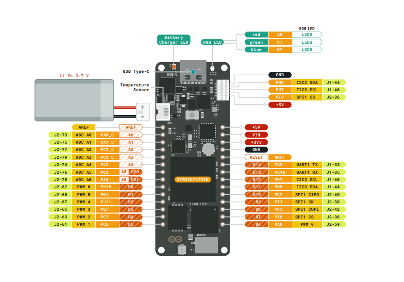
Hi, I am a beginner and this is a very basic one- could someone please guide me on how to figure if a board's got a pull-up/down resistor? Is the pinout sufficient? I am specifically looking at H7 Portenta
PC
Hi, I am a beginner and this is a very basic one- could someone please guide me on how to figure if a board's got a pull-up/down resistor? Is the pinout sufficient? I am specifically looking at H7 Portenta
PC
I think it is safe to say that all modern MCUs have pull-up and probably pull-down options built in.
There may be exceptions for certain pins, so check the processor data sheet, which is always your best source of information.
Hi @jremington, thanks for that! I also realised that Portenta pins are configurable. I am using Micropython to test a DC motor but every time I terminate the program when it's at "ON" mode, the motor continues to run indefinitely. I have defined the pin to be PULL_DOWN, thought that would solve the issue but it doesn't.
Nonetheless, happy to learn another thing about Arduino pins this way!
PC
Pull-up/downs are for input pins, not for motor output. Also, it's more common to use pullup than -down.
Feel free to post your wiring scheme and code...
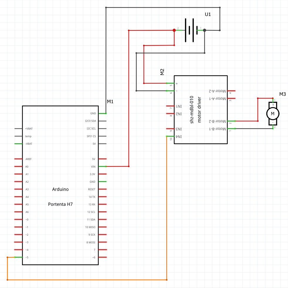
EDIT Here's the schematic (5V 3A battery used here):
Here's the schematic wiring setup:
And here's the code (sorry it's micropython and I know this is the Arduino forum so probably not the most appropriate):
import time, pyb

tim = pyb.Timer(8, freq=1000)
ch1 = tim.channel(3, pyb.Timer.PWM, pin=pyb.Pin("PH15"))
carousel = pyb.Pin("D5", pyb.Pin.OUT_PP, pyb.Pin.PULL_DOWN)

while True:
    print("carousel on")
    carousel.value(1)
    pyb.delay(1000)

    print("carousel off")
    carousel.value(0)
    pyb.delay(1000)
PC
Looking at your circuit you have the +ve from your battery connected to an unmarked pin of the Arduino. You do not show the voltage of your battery either, just the current capacity which is a useless figure in the context of your problem.
Basically we need a much better schematic from you.
Normally you would put a hardware pull down resistor for any problems with spuriously running of things during the power up sequence, even if you have a software capable pull down pin, because that pin only gets pulled down when the pin in initialised in the start up function.
Also any battery in a circuit should have a switch to turn it off to prevent parasitic powering when the power is removed from the Arduino.
FYI that's not a schematic. Yes, it's a wiring diagram. But a schematic follows certain rules, and omits all purely physical aspects of the circuit to make the connections easier to read and understand. A breadboard would never appear in a schematic, for example, because it's not really a component, it's just a physical means of wiring components together.
But back to your breadboard wiring diagram. Your Arduino looks like it's breadboard compatible, but you didn't plug it into the breadboard. Why is that? I've noticed a lot of beginners do it and I find it puzzling.
A word of warning: breadboards can't take large currents. They get hot and melt. Best to ensure nothing over about 1 Amp goes through it, unless it's only for a moment. Small motors might be ok, but it's generally safer to wire motors with thicker wires, off the breadboard. Those Dupont cables you can buy, with male/female connectors, are also not good for high currents, the wire inside them is very thin.
Hi @Grumpy_Mike, thanks for your inputs! I have updated the post with the schematic.
I see, thanks for explaining. I assumed it won't be necessary.
Thank you for the suggestion, shall include in the setup!
Hi @PaulRB, thanks for your input! I have updated the post with the schematic.
I usually do that with smaller Arduino's/Pi's, but here I am using the breadboard just create two channels with power from the power bank that I can connect my motor and Portenta to.
Thanks for this, will keep in mind!
This topic was automatically closed 180 days after the last reply. New replies are no longer allowed.