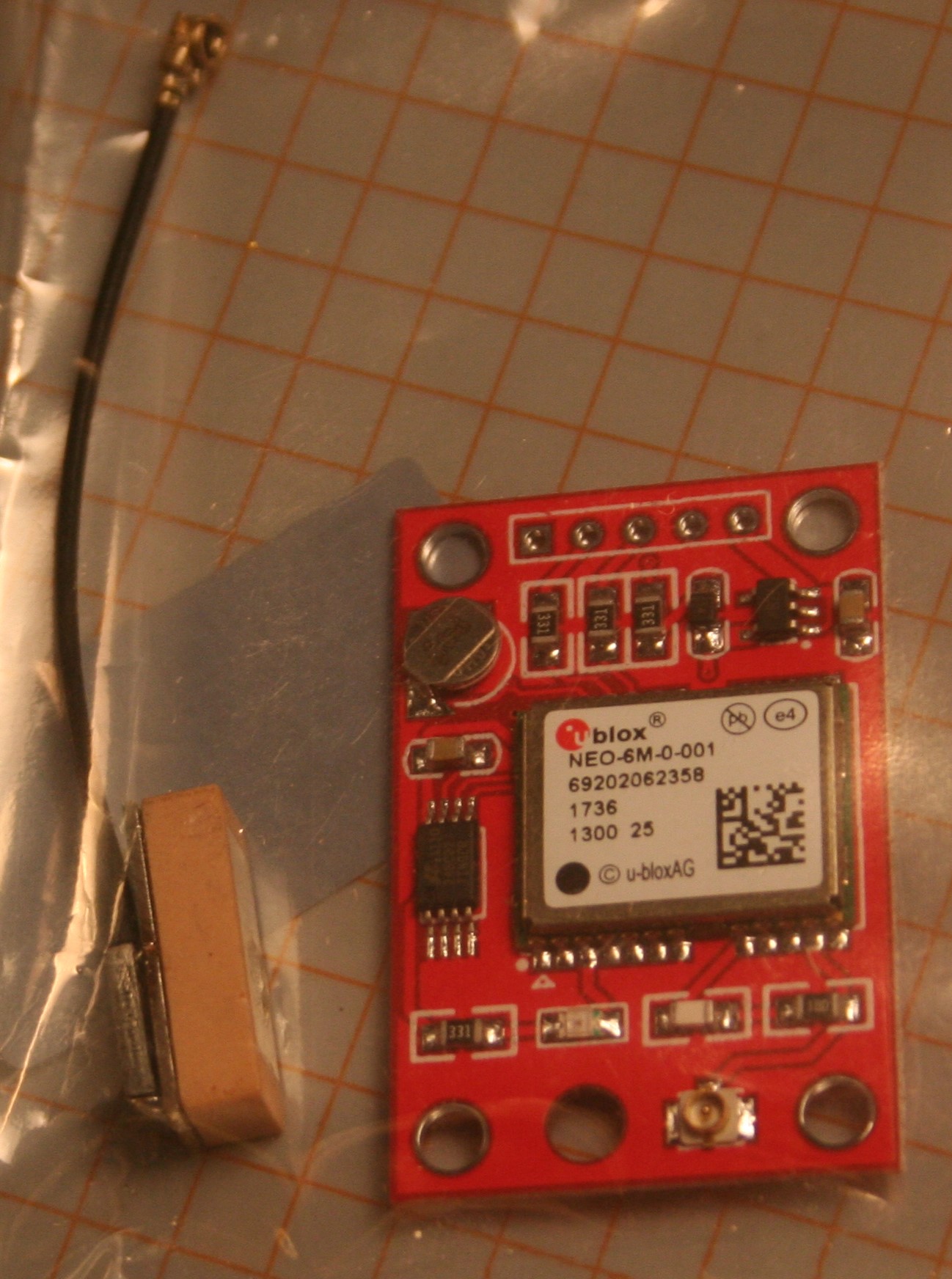
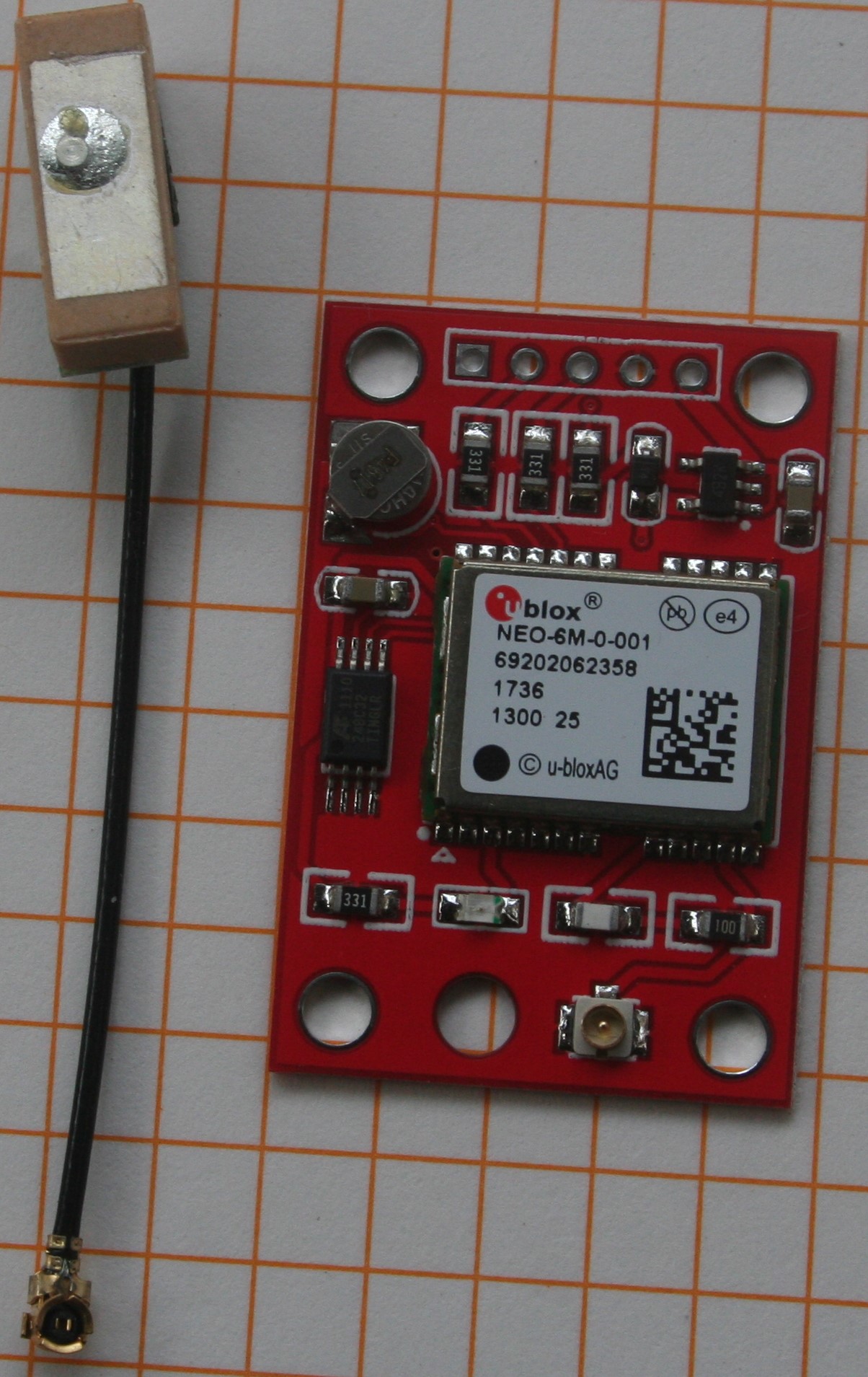
I purchased 2 of these GPS Modules https://www.ebay.com/itm/1Set-GYNEO6MV2-GPS-module-NEO-6M-GY-NEO6MV2-board-with-ante-KH/153567598622?ssPageName=STRK%3AMEBIDX%3AIT&_trksid=p2057872.m2749.l2649 (GY-NEO6MV2) from ebay they are, or claim to be, Ublox NEO-6M GPS engines. I set one up using a Pro Mini 3.3 V 8 MHz boards, the Pro minis work well for the project I have in mind given their size and cost, Having the option of 3.3 or 5 volts is great especially as more sensors are moving to 3.3 V, makes the interfacing much easier not having to use logic-level shifters.
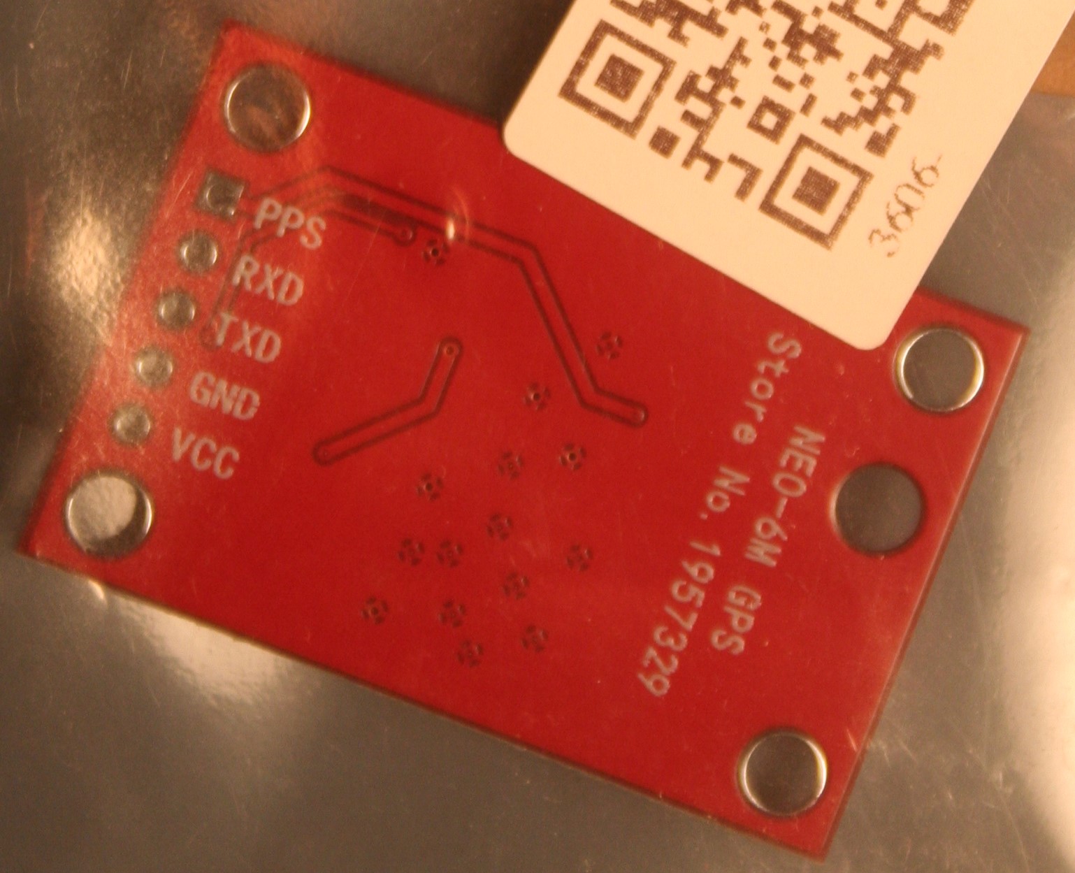
When I powered up the Pro Mini with the GPS power connected to the VCC and ground pins, the only connections initially just to check if any LEDs would turn on. When I powered up the pro mini no LEDs on the GPS module lit up at all. I thought maybe there is not a sign of life LED on the board showing when it has power. I tried many of the examples in the standard GPS libraries with no luck. I have interfaced GPS modules in the past with no problems, although this is the first time using these modules. The only power applied to the GPS have been from the Pro Mini so they are at 3.3V, I checked this with a DMM. I tried to the connection at all baud rates, after first trying 9600 and 4800 which are the baud rates of all GPS units I have used in the past. There was not a baud rate that the GPS worked.
Decided to make a simpler setup I connected the GPS to a 3.3 V FTDI TTL to USB convertor, I had been using it to program the Pro Mini with success so I am confident that the FTDI convertor works. The connections were RX on the FTDI to TX on the GPS module and TX on the FTDI to RX on the GPS. When I plugged in the FDTI once again I did not see any LEDs light up. The schematic http://wiki.ardumower.de/index.php?title=Datei:GY-NEO6MV2_schematics.jpg for the GY-NEO6MV2 shows an LED on the output of the voltage regulator so it should light up when power is supplied.
I fired up the Ublox U-center to see what would happen it could not find a GPS module connected at any baud rate. I fired up Putty to see if I would see any connection over serial monitor, there was no luck.
I tried the above with the second GPS module, same model number and vendor, I ordered both at the same time, and it did not work either. I have exhausted all of the possible ways of testing the modules that I can think of. I realize the price of these GPS are very low and I should not have great expectations for their performance but I would assume it would give me something.
Have any of you used these modules and had better luck than I have or do you have any recommendations?
Thanks
wade