As a preparation for another project about erasing scanlines on an RGB video signal, I'm starting from the bottom, and trying to figure out how to ground a signal. My Arduino helps out in this phase.
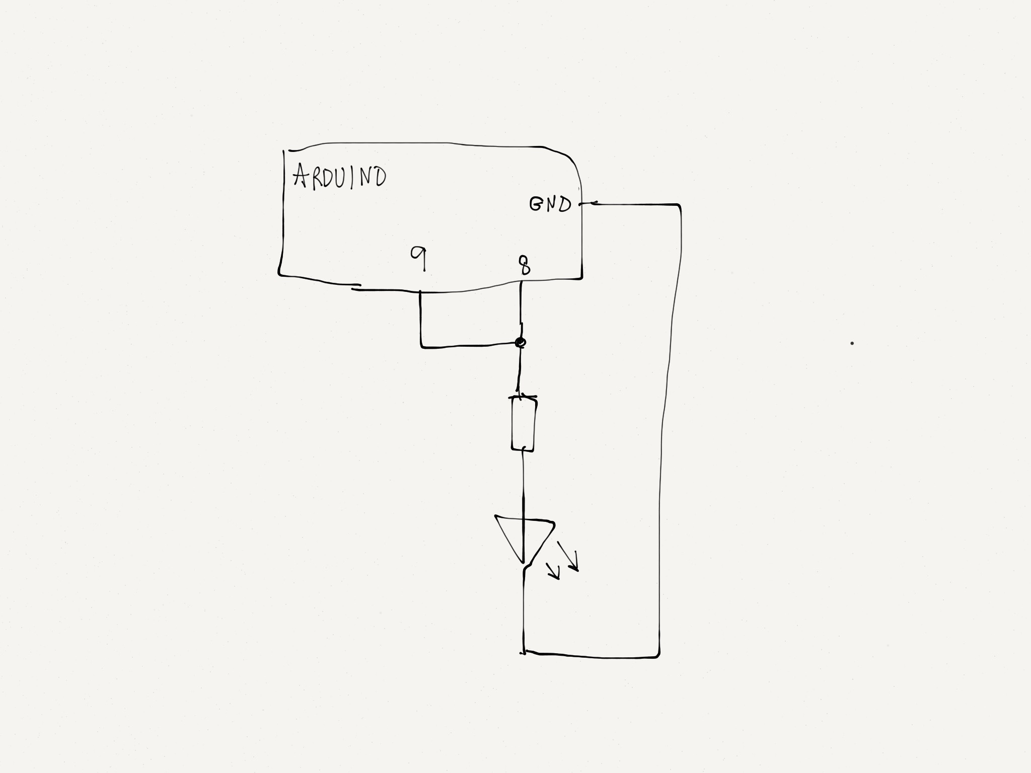
In the attached schematic, pin 8 is OUTPUT/HIGH, and pin 9 is INPUT/High impedance. LED ligths up as expected.
If I make pin 9 OUTPUT/LOW, the LED dims, but I want to make it go out completely. Maybe I'm even frying my Arduino now? Can I use pin 9 to somehow switch off the LED, without extra IC's, trransistors etc.?
The reason for me shorting out my Arduino, is a desperate attempt to understand how this scanline eraser works.
I use the Arduino to simulate the tristate buffer. I will of course use the real buffer ic once I understand how it works.
The buffer output is connected to the R, G and B lines of the VGA signal (three buffers). Buffer output = Z (high impedance) --> normal video signal. Buffer output = GND --> video signal blanked. Buffer output switches between GND and Z every other scanline.
The reason for me shorting out my Arduino, is a desperate attempt to understand how this scanline eraser works.
The difference between what you are doing and that circuit is that the video signal has a larger output impedance and so is pulled to ground much more easily than your test circuit. This has two outputs of equal impedance fighting each other.
Not sure what you are not understanding about that circuit?
The line sync pulses drive 74LS74 which is basically a divide by 2 circuit, so depending on the way the switches are set you get a signal that is high and low every other line or every two lines. Then this enables a buffer which switches a low, or ground, to the buffer's output or else leaves it as tri-state.
If it is low then the video is shorted out or else it is not.
Thank you - this is really helpful! What I did not understand was exactly the part about higher output impedance that makes the signal be more easily be pulled to ground!
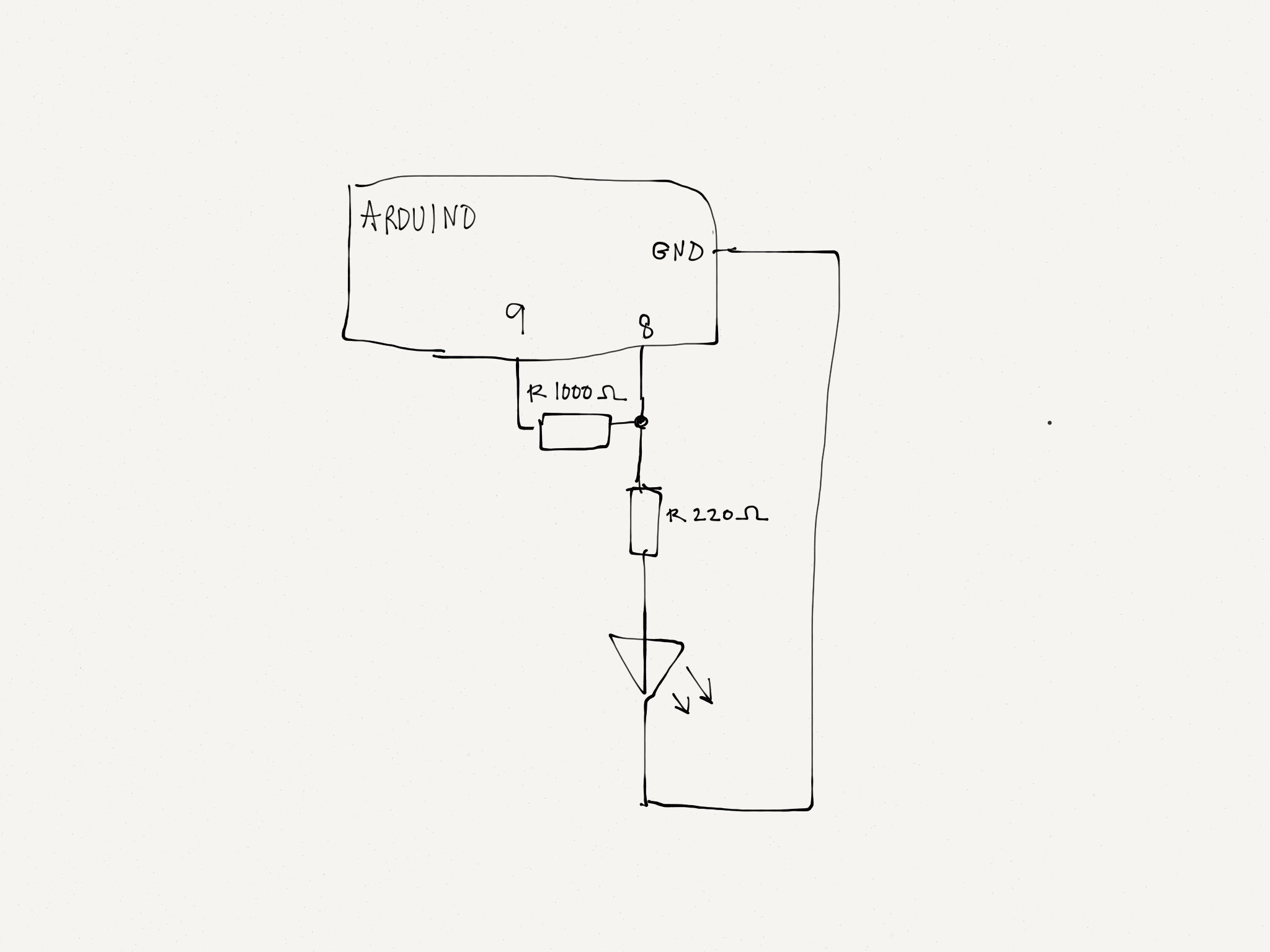
How can I adjust my little Arduino test circuit? Add a big resistor? And then do something so my Arduino is not shorted out...?
Put the resistor between pins 8 and 9. Then put the LED between 9 and the ground.
Make sure pin 9 is only ever set as an input, or an output with a logic low on it.
@Grumpy Mike: You suggest I connect the LED to pin 9? I imagine that the signal going from pin 8 through the resistor and the LED is one of the video signals (i.e. Red), and then pin 9 is the output pin of the video buffer. But maybe I cannot 'simulate' the scanline circuit this way?
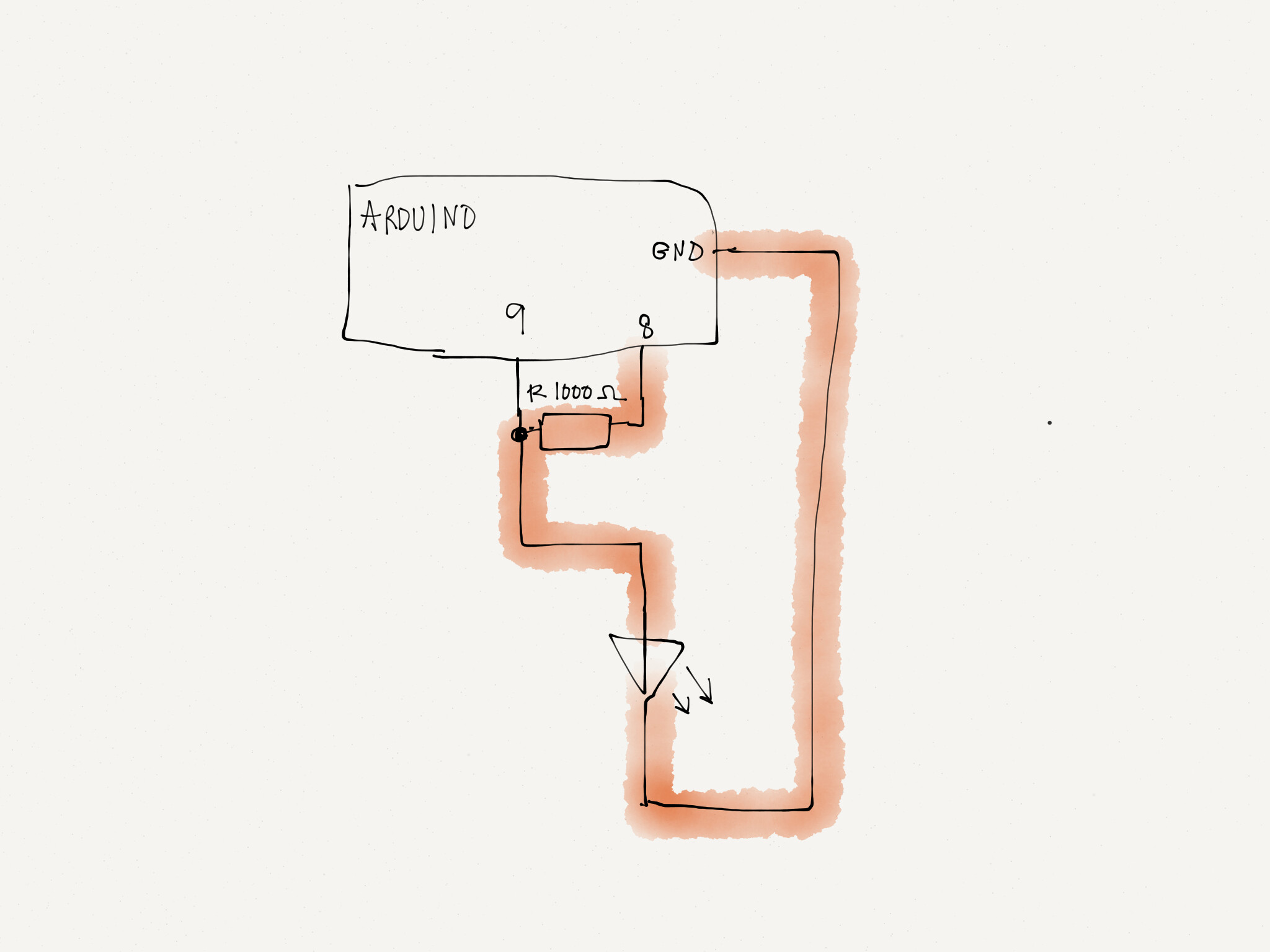
Sorry for the confusion. Now I believe I have set it up exactly like you said, Grumpy Mike (attachment), and it works great! Thanks! The red line from pin 8 to ground represents the video signal. Pin 9 represents the buffer output, that connects to the video signal line. When the buffer output is Z (high impedance), it is electrically disconnected from the video line. In my test circuit, the LED is on, representing the normal video signal. When the output goes low, the video signal is pulled low, and the LED turns off. In the video circuit, this will result in a blank scanline.
I know I'm in over my head with this video circuit, but I'am very much motivated to understand what goes on, and not just build from the schematics. Thanks again for your help - and your patience, Grumpy Mike!
Yes that's right, glad you got it going.
What exactly is the point of blanking out lines in a video signal?
Given the right circuit on the left hand side of that circuit you could blank out one specific line or a bunch of specific lines it you want, it is just a matter of counting the lines and generating a signal when the correct count occours.
You could just as easily use 3 2n2222 NPN transistors to pull the scan lines low using resistors to drive the
transistors. When they are off they are high impedance. The end result is the same. You can drive all three
with a single resistor so they are synchronized. (with 10 k pullup resistors on each transistor)
Why erase either even or odd scanlines? It is about achieving a retro gaming, arcade-like visual expression from an upscaled video output
I have a SEGA Master System console from the late 80's. My LED TV won't even output the low-res RGB video signal coming from it. So I bought an upscaler/line doubler card, that converts the low-res RGB to a high-res VGA. This works great.
Then I realized that I now have the option to blank every second line, without loosing something from the original video signal. Having these tiny black lines going across the video output 'emulates' the arcade cabinets' RGB monitor look and feel.
@Rasch: Thanks for the input. Interesting approach! I think I'll just go with mmmonkey's schematic - I have already bought the parts