Guide in designing circuit with Solenoid Valve (12VDC and 24VDC) interfaced with Arduino Nano


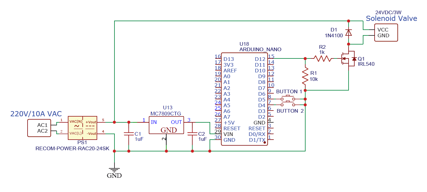
I am not of an expert and just beginning in electronics, I have tried to design this circuit. I will be doing 2 separate design, one for each solenoid valve that I'll be controlling using Arduino NANO. The 1st schematic is for the 24VDC-3W solenoid valve which I'll use to control a pneumatic cylinder (required to be quick release/retract of piston) and the 2nd schematic is for the 12VDC-4.5W solenoid valve to act like a gate valve to pass and stop the flow of air depending on the time I has set it to do so.

Q1. The first thing I want to ask is that is the power supply part, is my design okay or are there anything I should change? The Arduino NANO operates at 7-12V so that is why I tried to have voltage regulator MC7812 to output 12V from 24V AC/DC-830mA Power Supply (RAC20-24SK). Also in the 2nd circuit, I just used a power adapter labeled 12VDC, 1A to power both the 12V solenoid valve and Arduino NANO. Is it alright that solenoid valve and Arduino Nano share the same power supply?

Q2. I have used MOSFET based on the discussion here in forums and I see that they use IRF540 however, I am not sure if this will be compatible with connecting to Arduino nano. If anyone has extra time I am still confuse of the parameters needed to look for to tell when a MOSFET/transistor is appropriate for a design. I see that Vds, Rds_on, etc. are being described but I am a bit sluggish to understand how this be calculated to the chosen load w/c is the solenoid valve (I also had this IRLML6344 MOSFET that I consider to use instead of IRF540).

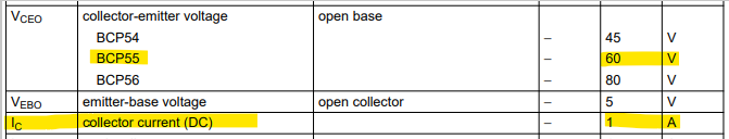
Q3. For the 2nd ckt, is the BCP55 transistor appropriate for my design, and is the resistor value of 10k appropriate? This is the only NPN transistor I have so I chose this one. Same question as to Q2, what parameters to tell that this is okay to use. What should be considered in calculations of voltage and current consumption should I look for given the power supply and solenoid valve I have.

Q4. I have seen that it is recommended to use 1N4001 for the flyback diode, but what I have is only the 1N4150, is this okay to use?

Q5. The 12VDC solenoid valve have this label, I just want assurance that it means I can get rid of the flyback diode on my 2nd circuit? enter image description here

Q6. I read somewhere that SSR and photocoupler can also be used when interfacing with solenoid valve, what I have right now is for SSR, AQY212S for photocoupler: TLP-182, TLP-785-GB, TLP-523-1, TLP-627M. I am not familiar in interfacing this within my circuit.

Here are the links to the parts list:

24VDC-3W-N.C Solenoid Valve - https://docs.rs-online.com/20a7/A700000008651199.pdf

12VDC-4.5W-N.C Solenoid Valve - https://docs.rs-online.com/b218/0900766b815dd865.pdf

24V AC/DC-830mA Power Supply - https://recom-power.com/pdf/Powerline_AC-DC/RAC20-K.pdf

BCP55 datasheet - https://www.mouser.ph/datasheet/2/916/BCP55_SER-3081565.pdf

IRLML6344 - https://www.mouser.ph/datasheet/2/196/Infineon_IRLML6344_DataSheet_v01_01_EN-3166606.pdf

Great job on the Schematics. I like the first one the best. I would not use the MC7812 regulator it will run very hot for you. Instead get a Buck Regulator, they can be very inexpensive from your favorite china supplier. This will keep you to one power supply. Use a second buck for the 12V solenoid then you only have to build one system. You are correct a Different MOSFET would be better as the Vgs is to high for logic level switching. For power supplies you need to check the wattage. The IRLML6344 would work but will be close with the 24V system. That is a 30V Vsd (source drain) you want at least 40.

I would not use the transistor but a MOSFET instead. The transistor will get quite warm. If you use the transistor check your base resistor it is not passing enough current into the transistor. In the second schematic you have 12V feeding the TM1637, that will fry it. Sorry I am out of time, good luck, Later

2 Likes

In the first schematic diagram, the IRF540 will not work with Arduino, and you are lacking the required gate resistor (1K is OK). You also need a gate pulldown resistor (10K). Use a logic level MOSFET such as IRL540 instead.

The BCP55 is fine for that solenoid in the second diagram, but the base resistor R4 is far too large. Plan on current gain of 25, as per the data sheet, and use 220 Ohms for R4.

I agree with the above that 12V is too high for the Arduino Vin. 7-9 V is much better. Better, use a 5V stepdown converter and power the Arduino via the 5V pin.

1 Like

I agree, both that your schematics and presentation of your questions is excellent, and what @gilshultz and @jremington have to say about the regulator and FET, maybe more.

In your first schematics, what is the purpose of VD6?

1 Like

Hi thanks for the reply and for correcting me about IRL540 I didn't notice I used the wrong mosfet. I did what you suggested adding gate pulldown resistor of 10k and gate resistor of 1k.
Also changed R4 to 220 ohms as what you have said.

This arduino nano has this:


I tied it to the 12V so I can get rid of adding voltage regulator (let's say MC7809) for a 9v.

Would like to ask using the power MOSFET, can it be driven by the output pin of the Arduino? or should there be external small signal transistor before the MOSFET?

Added VD6 as seen on other design, I thought it was for protection. but I edited already and get rid of it.

Thanks for pointing out how I should not settle for IRLML6344, I will use IRL540 as what @jremington suggested.

And yes, I forgot that TM1637 has max of 5V for its operating voltage.

I thought it was for protection

It would've been there to protect the regulator from backwards current, but I can't see how you could possible power your arduino so that diode would be necessary. :+1:

1 Like

Hi,
Have you calculated your solenoid currents?

24Vdc 3W
P = V * I
I = P / V
I= 3 / 24 = 125mA

12Vdc 4.5W
I = 4.5 / 12 = 375mA

What model numbers are your solenoid valves, you link to data sheets that have the whole range of units in them.

Thanks.. Tom... :grinning: :+1: :coffee: :australia:

1 Like

You can. Some swear upon a resistor is needed between output pin and FET gate, other say it's a myth. In your case, you're not doing any PWM, so you should be safe (I take no responsibility if a pin of your Nano bonds with the PCB or mates with the cat)

1 Like

Hi there yes I have calculated the load current, and it's ofc the same as what you have presented.

For the 24VDC solenoid valve it is the specific datasheet, as for the 12VDC it is the VX210 C Z1E model (solenoid valve for air - 12VDC grommet with voltage surge suppressor)

And some people say the earth is flat.

The resistor is needed. Science has proven it.

1 Like

Here's some of that flat earthers reading:

https://forum.arduino.cc/t/myth-busters-3-myth-you-must-have-a-gate-resistor/172841

It's long, so brew some tea or coffee and put your mobile in DND.

I read the first several posts in that thread and have no interest in reading an argument between devotees of both sides. I have no interest in arguing the point with you either. Especially if we hijack this thread to do it. No one’s mind will be changed.

I will do me, you can do you. I will trust my knowledge and you yours.

2 Likes

I agree. Also that there is no point in arguing with people who choose to believe otherwise.

4 Likes

hi, just want to clarify more how were you able to pick 220 ohms for R4, what parameters for calculating the value did you consider? I believe current gain of 25 is this part of the datasheet:
image

this is how I edited my schematic,

That value of resistance provides the maximum base current, subject to the recommended maximum current draw from a Nano port pin (20 mA).

(5.0-0.7)V/220R = 19.5 mA (Vbe = 0.7V)

The minimum DC current gain required for the solenoid current Ic = (4.5W/12V) = 0.375A would be 375mA/19.5mA = 20, which that transistor easily meets (data sheet says hfe=25 minimum @500 mA).

1 Like

thanks for providing the calculation and clarifying my question, it's much appreciated.

Just a little inquiry again, am I correct if I explain the use of BCP55 transistor using this statement:

"The Vceo (maximum collector-to-emitter voltage) rating of the BCP55 NPN transistor is 60V which is higher than the 12VDC supply voltage and has an Ic (collector current) of 1A which is greater than the current required to drive the solenoid valve. These parameters of the chosen transistor ensure safe operation considering there are margins for safety."

given that this is the content of the datasheet I am referring to:
image

or are there any critical parameters of BCP55 that I should highlight to justify why it is compatible to use with my design being interfaced with Arduino NANO and 12VDC-4/5W solenoid valve.

To add, should I be concern about thermal considerations of BCP55 transistor on how it handles heat dissipation? not so sure on how I decide on how it can handle power dissipation when controlling solenoid valve.

moreover, if it is okay, may I know your comment in how I explain the design as per your suggestion:

Base Resistor Selection

In this circuit, the base resistor is a crucial component that controls the current flowing into the base of the BCP55 transistor. To ensure that the Arduino Nano port pin can safely drive the transistor, the base current must be limited to 20 mA (recommended maximum current draw form a Nano port pin).

IB= (Vbatt-Vbe)/RB=((5-0.7)V)/220=19.5 mA (Vbe=0.7V)

The voltage drop across the base-emitter junction of the transistor (Vbe) is typically around 0.7V. Given a supply voltage of 5.0V, Ohm's law (V = IR) is used to calculate the necessary resistance. Rearranging the formula to solve for the current (I) yields I = (V - Vbe) / R.

Plugging in the values, we get (5.0V - 0.7V) / 220Ω = 19.5 mA. Therefore, a 220-ohm base resistor is chosen to ensure the base current is limited to 19.5 mA, which is safely below the 20 mA limit set by the Nano port pin.

Minimum DC Current Gain (hFE)

To determine whether the BCP55 transistor is suitable for the application, its minimum DC current gain should be considered. In this case, the solenoid requires a current (IC) of 375 mA to operate correctly. To control this current, the transistor must provide sufficient current amplification.

The base current (IB) required to achieve this collector current is determined by the ratio of collector current to hfe (IC / hFE). In this specific case, 375 mA / 19.5 mA equals approximately 20.

375mA/19.5mA=20

Therefore, a minimum hFE of 20 is required to ensure the transistor can provide the necessary current amplification. The selected transistor, BCP55, meets this requirement because its datasheet specifies a minimum hFE of 25 at a higher collector current of 500mA.

Correct. Re heat dissipation: the transistor must not exceed 1.33W total power dissipation, which is Vce*Ic, subject to Note 1 below the table in the data sheet. Vce is the collector to emitter voltage measured when the solenoid is on.

1 Like