I recently made a ceramic kiln with a simple REX C100 (one of the cheap aliexpress version).
It works fine but it can be very tedious to always be close to the kiln to follow the firing stages as it should be (gradual temperature rises, temperature stages, etc.).
So my goal is to "hack" the PID Controller with an ESP32 that can allow me to have a graphical interface in order to select/modify the firing schedules.
I'm a bit new in electronics so I feel like posting here can save some of my hardware while helping other people (if we find a sleek solution together)
My goal is to wire an ESP32-C6 to the REX C100 buttons and to the Led display (or the chip controlling it) in order to allow the ESP32 to read and interact with the controller directly (as an human user would do).
I don't want to replace the whole REX C100 by an ESP because I'm satisfied with the way the PID handles temperature and shows current and targeted temperatures.
There's three challenges in this project :
[Crutial] - Simulate panel buttons actuation.
For that, I feel like the easiest way to do so is to shunt the push buttons with transistors like I did in that simulation I made (sorry it's a bit messy) : Circuit design Arduino Read 4 digits 7 segment display + push button + led - Tinkercad
But I'm not sure which transistor I should use, I often see 2n2222 used, what do you think about it ?
Do I need to be careful of anything else ? The REX C100 work on 5v and the ESP32-C6 in 3.3V, so maybe it will not work the same way as in my simulation ?
I put a random resistor to protect the base of the transistor, but I don't know what resistance value to set, or even if a resistor is useful here.
[Good to have] - Reading the LED panel.
This feels more difficult... This controller features a 2-line, 8-digit 7segments (+ dp) display with 16 pins. I think its a common anode. I didn't find the datasheet for this display.
Also I think this led display is drived by a MAX7219, it's not written on the chip but there's 24 pins on it and it's the most common chip used on this kind of display (according to my google searches )
I tried to read the I2C pins (GND/DSDA/DSCK/5V) next to the led display with a basic logic analyzer but I didn't find any understandable pattern
I'd like to use as few pins as possible in order to read it, so I feel that the solution is to read the inputs of the (alleged) MAX7219. But if it's not possible, I think I'm going to have to read the 16 pins of the display...
[Bonus] - Reading the leds.
There's 3 leds on the panel, one that lights up when there's an issue (ALM = alarm), one for when the kiln is heating (OUT), one that I don't know the usage (AT)
I think it would be nice to have a LED reader just to show on the ESP graphical interface, if these leds are light or not.
I'll be grateful for any help, and excuse me if I've not specified something, I am ready to give you all useful information and change my initial post for more clarity if necessary.
Bypassing the PID control means you will be writing the PID control.
I have a thermostat in my house that has a heating profile that operates on (1) day of week, (2) time of day, (3) temperature. It either has an issue with network, power, wifi reception, or something else. Before that I was turning a knob only on when it needed. Seriously, I was less involved (more happy) with the boring knob than the highly integrated, network based controller. Don't let my boring anecdote stop you.
Yeah, I'll try not to burn/electrocute myself with the high voltage, that's always good to be reminded !
I'm not trying to bypass the PID control but to interact with it like an human would do (but automated with the ESP32) so only read the numbers on the display panel and "write" by pressing the buttons.
It would have been nice if I could stuck to boring buttons, but firing can take up to 12-14 hours (and even more). So it would be really cool to be able to start it whenever I want, even by night (the cost of electricity can be lower at night where I live)
And simulating a progressive rise in temperature by manually setting the target temperature is a pain in the a**
Damn it's exactly that and it's way cheaper than the ones I saw when I was building the kiln!
Thanks for the link!
Tbh, I think I'll keep on looking for a “hack” method, just because I love learning how things work and electronics have always been an intriguing universe to me! I'll learn by trial and errors, and if I don't come up with anything satisfactory, I can always order that Ramp/Soak contoller!
One potential problem is that if you get out of sync with the Arduino's idea of the state of the REX-100 Ui, and the actual state of the UI, it could screw things up badly.
Solving your point 2 helps, but decoding the display state into the UI state will be awful compared to the commodity soak controller.
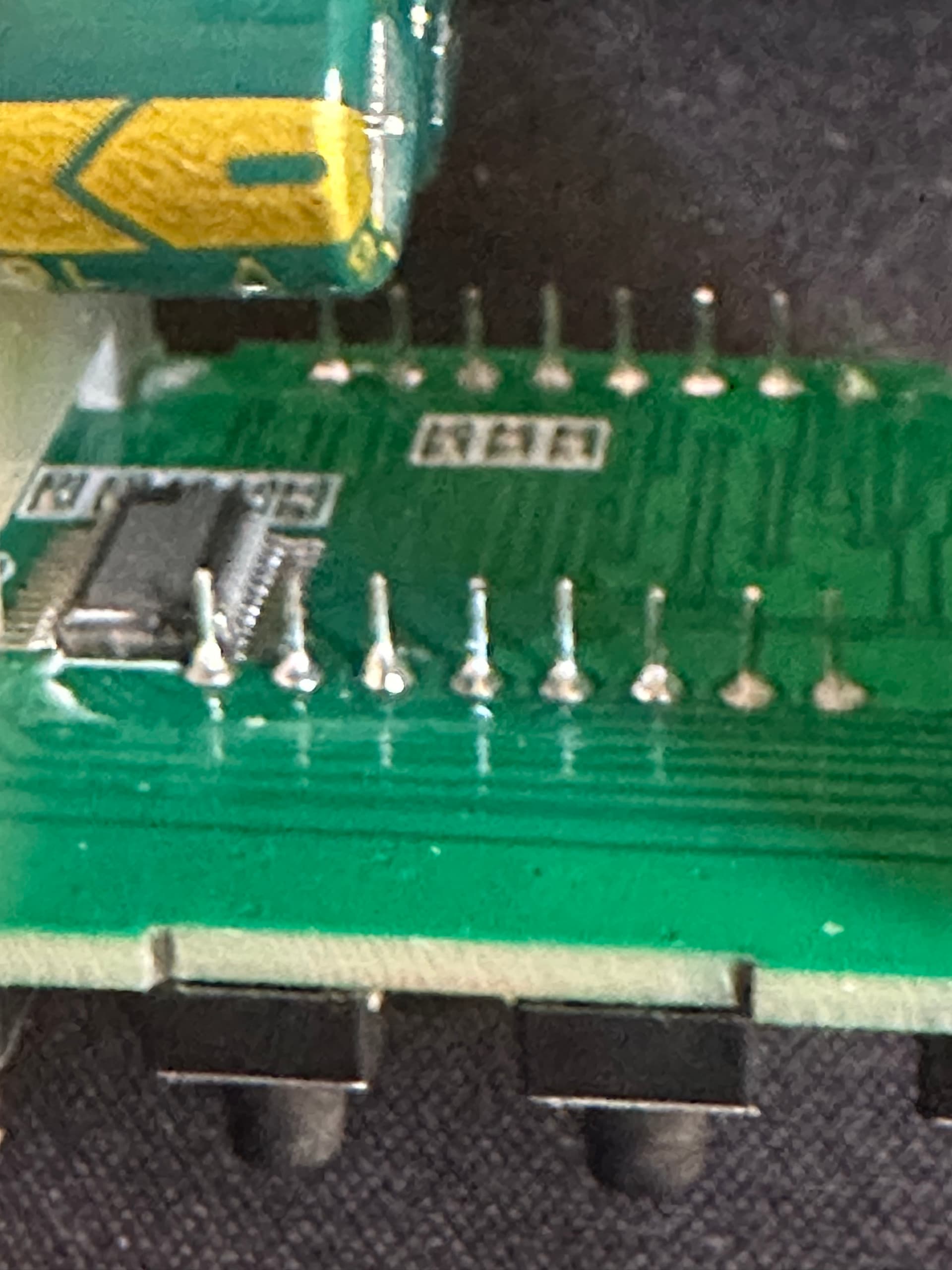
To continue the thread about this hack; the alleged MAX7219 wasn't a 7219 at all... the pinout doesn't match. So I guess it's a proprietary chip.
So I guessed (pretty much) all the pins by analysing the pcb traces, and analysing the inputs signals with a logic analyzer.
Unfortunately I couldn't figure out the signals going into this chip, so I decided to plug the ESP directly to the pins of the LED display.
After some hours of soldering, trial and errors... I managed to obtain the 8 digits on the ESP side in a "stable" manner (one reading error on one digit out of > 1000 correct reads).
Next step : plug all those wires on an TCA9548A MCP23017 extension board in order to free gpio on ESP32 for the "simulate buttons actuation" phase.
Just a quick update on my hardware hacking journey:
I've been working on the REX C100 and managed to get something roughly functional.
However, the way the ESP32 GPIOs are currently connected to the REX C100 is causing some issues during the ESP32's boot sequence. The GPIOs aren't in their expected states at boot time (which makes sense, since it's still booting ), and this ends up blocking the ESP from starting properly...
I’ve lost a bit of motivation on this project because of that new challenge (and because I have other projects that are piling up), so I’ve decided to simply buy a ramp-soak PID controller, as @cedarlakeinstruments suggested, and share the code with the community in case anyone wants to take it further.

 )
)