I'm trying to read position feedback by a linear actuator using Arduino Mega and a motor driver.
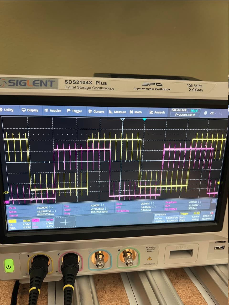
I can see that the hall effect sensor is picking up the frequency of the input PWM from motor driver and causes false pulse reading therefore false position reading (I am using interrupts to read the pulses).
Is there anyway to reduce this noise? Is this the design flaw by the actuator or the motor driver causing the issue? or the frequency I am using for PWM or anything else?
The max frequency of hall effect is 200Hz and PWM frequency is 4000Hz. As you see there are about 20 spikes per cycle.
The motor gets 12V, Max 5A as input and the hall effect gets 5V.
I have tried to separate GND and Power lines but that did not help and I am trying to avoid using RC filters.
So the layout is pretty simple. Arduino Mega 5v pin is powering the sensor. another 5v pin of arduino Mega is powering the motor driver. And the motor driver gets it high power from a power supply of 12V and 5A and feeds its PWM to the actuator.
Unfortunately I do not have a pic of the board or the schematic right now. I can provide that later.
The scope probe is only connected to the Hall signal. did not know they have gnd too or if that matters.
Is that going to affect how I scope the signal on the display?
Everything is relative to something... It's only 5V is there is a ground (other path). It's common for birds to sit on HV lines... no ground (return) path, no current flow..
Your description seems to indicate you have it working. If you have no other access to the motor, have you checked power to the hall sensor for any anomalies.?
Yes it will, you will have no project gnd reference for the signal that the scope is displaying.
This will make your display susceptible to all sorts of noise, including from the PWM.
What actually is the scope looking at, it looks like an encoder quadrature signal?
Can you please post links to data/specs of the actuator and the Hall Effect Sensor?
I did connect scope probe gnd to the board gnd. its showing the same noisy signal. I wish I could get some info on their hall effect sensor in the actuator. But the website and the data sheet does not give out any info.
All I see is their hall effect sensor is picking up the pwm frequency and Im not sure if its some thing on my side or their design is flawed.
What is y our motor driver?
Can you please post a link to specs/data.
A schematic would be good about now and some images of your project so we can see you component layout.
The code you are using at the moment would be helpful, so we can advise on how to help.
You need to regard the position signal as an encoder, specifically a quadrature encoder, the are Arduino libraries that can read these devices for you.
The problem turned out to be a noisy PWM input from my motor driver.
I was using "VNH5019A-E" and I switched to " BTS7960" and I do not get any noise on hall effect signal anymore and number of pulse counts reads perfectly accurate.