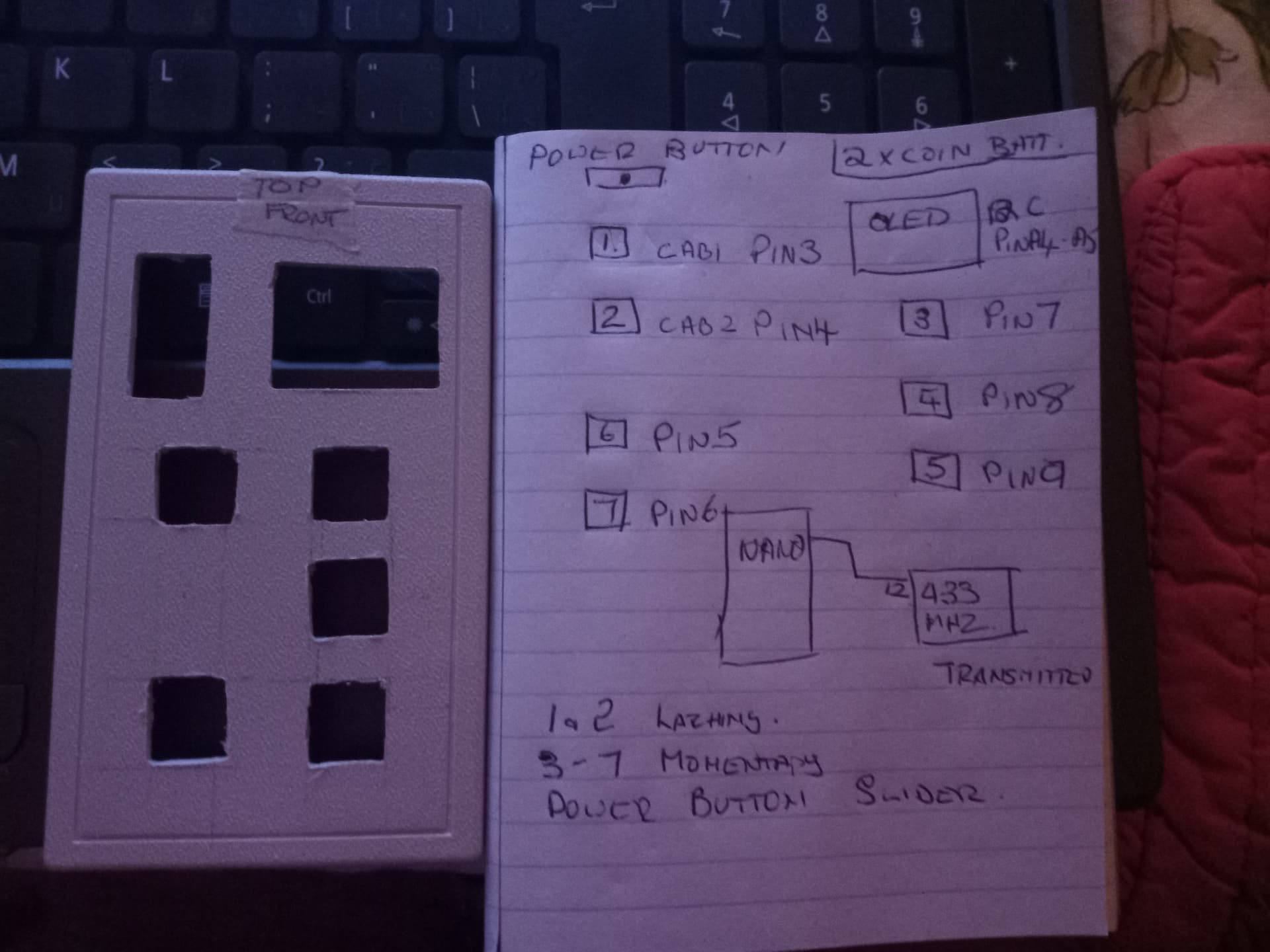
I have a breadboard that uses 7 buttons, 433mhz transmitter and a oled on a nano.
I need to transfer these items into a hand held case, as space is limited I was wondering if there was a way to cut down on the number of wires especially the ground wires and perhaps the buttons to the pins .
I may not be describing this appropriately so let me know if more information is needed. I do not have a schematic -
my buttons use INPUT_PULLUP.
This is a hobby of mine.
Any suggestions would be appreciated,
OK is it possible to wire the ground from the first pin to second pin etc down the line and then attach the ground wires from the OLED , the 433 and the power coming in.
I don't see why wiring would be the limiting factor here.
When I have a problem like this, if I'm not going to make a PCB, my process is to start with physical layout. Get the largest perf board that will fit in your enclosure. Don't forget to account for a battery if this is going to be portable, and make sure you have access to the mounting bosses in the enclosure (drill holes right away so you don't forget). Next, draw the desired layout (you already have that). Then temporarily place the devices on the perfboard, along with battery, charger, etc. into the enclosure and close it to make sure everything fits.
Once that's done then you can see the best path to wire everything together. It's usually good to start with putting down Ground and Power lines (bare wire) on the perfboard to make connections easier. Yes, you can wire ground as you mentioned above, but that makes it harder if you need to swap out a component.
With the exception of Gnd & power, I'd wire everything here with 30gauge wire-wrap wire. Possibly 22gauge for GND & +. There should be plenty of room for everything going by the size of your cardboard cutout.
Thank you s much for this guide, I shall give it try this weekend and let you know.
Can you give me more ifo on bare wire - what kind and where does one obtain it from.
Thanks again - will followup --
Power switch, Arduino on perf board, display mounted with hotmelt glue, Ribbon connector makes easy assembly. Batteries in battery compartment with push buttons on top of battery compartment using 2-part exoxy.
You can buy solid or stranded wire from Home Depot or a hardware store if you desire. By bare wire, I meant take insulated wire and strip off the insulation. Off the shelf bare wire is typically enameled and it's a pain to remove the coating.
You can buy this at any electronics distributor. Here's a hobbyist-friendly one. Any of the 30gauge Kynar wire spools will be good. Blue and white seem to be the most commonly used colors but it really doesn't matter.