I need your help on a project basic info of this project:
Arduino Uno R3
BT communication master/slave
Encoder function sent from master to slave
*other function used but working well
So basically what I'm trying to do is to fool an harware controller on a machine to make him think the machine is working (for service purpose).
So almost all my functions are working but I send the wrong infos to the hardware: I simulating a sensor sending different tension to the controller from 0V to 5V using an encoder.
My issue is:
I'm generating my tension on the PWM port of the arduino, it works well with a LED but the controller is receiving the 5volt and it is saying that there is a short-circuit.
What I need is to be able to send a continuous tension from 0v to 5v.
Ex: if I need 2v I need 2 volt all the time and not a cycle of 5 volt which make an average of 2volt (PWM).
Any idea how I can fix this?
Maybe a different port?
Or an electronic component?
A particular coding?
Transforming a PWM-voltage that alternates between Vcc and 0V can be done with a low-pass-filter
Here is a thread with pictures how such a low-pass-filter looks like.
You will have some up/down of the voltage with a fraction of the averaged voltage
This is called ripple
How much rippling you have depends on the capacity of the capacitor
increasing the capacity lowers the ripple but also lowers the reaction-speed to changes
Of course there are a lot of chips that can do DAC.
one example
If you describe how fast your voltage changes 10 times per second or once every few minutes a more precise answer can be given
What is "one grade per second" calculated to volts per second?
The equations of low-pass-filters work with slew-rate = olts per second
not "grade per second" (whatever this "grade" is
5V / 20 = 0.25V per position which equals to 0.25V per second.
This is a pretty low speed.
So if changing from 1.00 V to 1.25V takes 0.05 seconds would be fast enough.
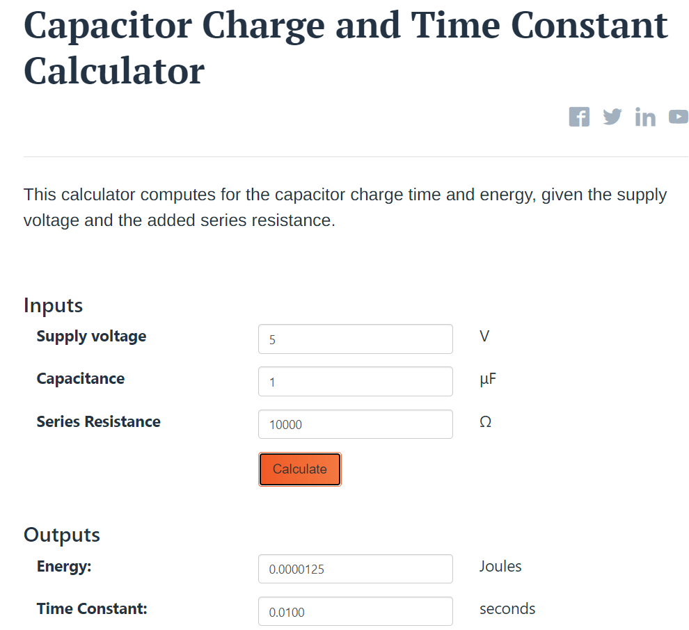
Here is an online calculator for the time-constant of a RC-lowpass-filter
At a voltage of 5V when using a 10 k resistor combined with a 1 µF capacitor the time-constant is 0,01 seconds.
Where the voltage changes from 0V up to 5V * 0.368 = 1.84V within 0,01 seconds
should be fast enough.
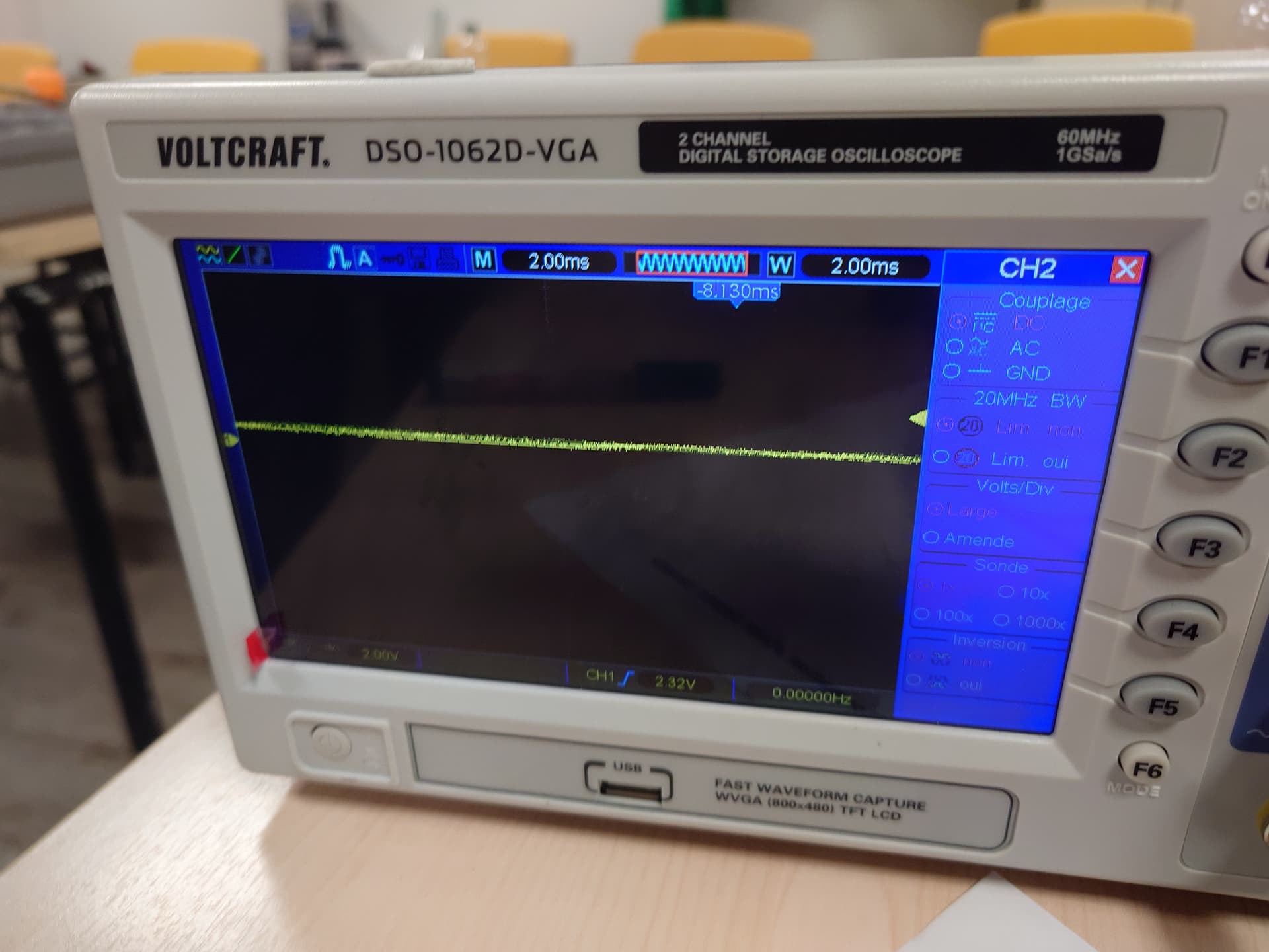
If you would like to know how much ripple is still there you could switch your oscilloscope to AC and change to 200 mV, 50 mV, 20 mV ... per grid point
to measure how much ripple is still there.
additionaly yo could write a testcode that changes from duty-cycle 10% to 90% with different speeds and then put the oscilloscope into singleshot mode to see how fast this change is happening
Same thing for changing from duty-cycle 90% to 10%