HC-SR04 and LCD I2C on standalone atmega328

Hello, everyone! Hope everything is ok!

I’m having a problem with prototyping: i want to use a standalone atmega328 to power a HC-SR04 to give me the distance from some objects when i press a button, then show the distance in a 16X2 LCD. However, whenever i power the atmega, there’s nothing on the serial monitor and nothing on the LCD (the letters appeared one time, but when i unplugged and plugged it again they never appeared again).

Things to keep in mind:

  • I do use a USB to TTL converter
  • I se an external bootloader that works, as i tested the “blink” example on the standalone atmega and the led blinked normally
  • I have the atmega setup with the 16MHz crystal, capacitors etc
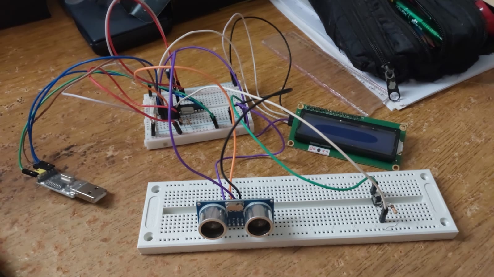
  • I’ll send the code and images here, but pinning is as follows:

USB/TTL: - RX on 0 (pin 2 of atmega) - TX on 1 (3)

HC-SR04: - trig on 2 (4) -echo on 3 (5)

LCD with I2C (skech dosen’t have I2C but real one does): - SDA on A4 (27) - SCL on A5 (28)

Here’s the code:

#include <Wire.h>
#include <LiquidCrystal_I2C.h>

LiquidCrystal_I2C lcd(0x27, 16, 2);

int trig = 2;
int echo = 3;
int botao = 4;  // botão no pino 4

void setup() {
  Serial.begin(9600);
  pinMode(trig, OUTPUT);
  pinMode(echo, INPUT);
  pinMode(botao, INPUT_PULLUP); // botão com resistor interno de pull-up

  // Inicializa o LCD
  lcd.begin();
  lcd.backlight();
  lcd.clear();
  lcd.setCursor(0, 0); 
  lcd.print("Pressione o botao");
}

void loop() {
  // Espera o botão ser pressionado (nível LOW porque tem pull-up)
  if (digitalRead(botao) == LOW) {
    long duration;
    float mm, soma = 0;

    // Mensagem de medindo
    lcd.clear();
    lcd.setCursor(0, 0);
    lcd.print("Medindo...");

    // Faz 100 medições
    for (int i = 0; i < 100; i++) {
      digitalWrite(trig, LOW);
      delayMicroseconds(2);
      digitalWrite(trig, HIGH);
      delayMicroseconds(10);
      digitalWrite(trig, LOW);

      duration = pulseIn(echo, HIGH);
      mm = (duration / 29.0 / 2.0) * 10.0; // agora em milímetros
      soma += mm;

      delay(20); // intervalo entre medições
    }

    // Média das 100 medições
    float media = soma / 100.0;

    // Mostra no Serial Monitor
    Serial.print(media, 1);
    Serial.println(" mm");

    // Mostra no LCD
    lcd.clear();
    lcd.setCursor(0, 0);
    lcd.print("Distancia media:");
    lcd.setCursor(0, 1);
    lcd.print(media, 1);
    lcd.print(" mm");

    delay(1000); // evita repetir rápido se botão ficar pressionado
  }
}

Could you guys help me figure it out what i’m doing wrong? I’m a novice in this.
Thanks in advance!

I hope you had the power turned off before your did this!

What do you mean?
The LCD still works normally

So, which is correct? If the letters appeared one time and never again or now it works all the time?

From the poor picture I can determine it will probably never work. The display you show needs a parallel interface, not I2C. You need to add a backpack or something similar to it if you want to use I2C.

Your SR04 and display do not have any power.

Have you tested the circuit using an Arduino board like Uno or Nano?

If not, do that first. Then, when it's working, move on to testing with a standalone ATmega chip.

Hello!
I do use it.

Hello, Paul!
Yeah it works normall on my arduino Uno, but when i try on the chip it dosen’’t :confused:

Hi, @nevermore_revenge

Can you please post a copy of your circuit, a picture of a hand drawn circuit in jpg, png?
Hand drawn and photographed is perfectly acceptable.
Please include ALL hardware, power supplies, component names and pin labels.

Thanks.. Tom.... :smiley: :+1: :coffee: :australia:

Hey there, Tom!
Never done this before so i’m sorry if it’s rough. Tried to do it based on what’s on my protoboard.

Your picture did not show that, that is why we ask for an annotated schematic. From your schematic it appears you do not have pull up resistors. Some of the back packs have 10K some of the older ones did not. The next thing to do is run the I2C scanner, there are many versions on line. If it shows nothing swap SCA and SCL and run it again. I am assuming the display lights up and the backlight jumper is in place.

I don't see any bypass caps. You need 2x 0.1uF ceramic bypass caps for ATMEGA328. Connect them between the 2x Vcc pins and ground, close to the chip.

This might not solve the problem, but it's important to have these bypass caps in any circuit, otherwise it can misbehave strangely. When you were using the Uno, those bypass caps are already on the Uno board.

Pins 20 & 22 sould be connected directly to the 5V and ground pins of the USB-TTL adapter. I don't think it's good to rely on the chip's internal connections to power the sensor and LCD like that.

I’ll give it a try, thanks!

Hi, @nevermore_revenge

Have you checked as to how much current your "Notebook" can supply on its USB?

Tom.... :smiley: :+1: :coffee: :australia: