As my first project I am using an Uno to control turning the headlight on a motorcycle on an off to send messages in morse code. I am struggling to determine how to not just properly wire the electric source from the motorcycle (power comes from stator to regulator and then voltage divider) but then send the proper power (not just 5.5V) to the headlight switch.
What is the best way to wire this and can I achieve my goal with my current hardware?
Your data rate will be slow as you will need significant time between pulses for the element to cool - if you look at ship to ship morse ; they leave the lamp on and have shutters in front of it to blank the lamp out .
Your data rate will be slow as you will need significant time between pulses for the element to cool - if you look at ship to ship morse ; they leave the lamp on and have shutters in front of it to blank the lamp out .
And the highway patrol will stop you for defective head light. Better to use the horn like everyone else does.
Can the MOSFET plug into the Uno and all the wiring be kept on the Uno? I am trying to keep the setup as compact as possible to fit inside the smallest enclosure I can get away with. I understand your diagram jremington, but how could it be connected to the Uno, are there other options than getting a breadboard?
I found this project and it helped my understanding but there are differences from what I am trying to do. Arduino MOSFET LED Driver Circuit - Engineering Projects
I understand how this could sound like a ridiculous and impractical project. I am building a custom motorcycle that is not street legal. It is a show bike with the theme of a secret agent escape vehicle. The motorcycle did not come with a headlight or powerful enough electrical system to handle any lighting. I have upgraded the stator (part of bike that is attached to the engine to create electricity) added a regulator and sourced a LED headlight and brake light so I know there are no sensors and if wired correctly will not pose an issue. I believe I just need to figure out the correct way to wire the Uno to the headlight switch so it works as designed and the rest of the wiring for the bike will not interfere.
The bulb is rated to last 30,000 hours and is more than adequate brightness at 2,500 lumens. Is there a way to predict how this will shorten the life? I am not planning on leaving the light in flashing morse code mode for more than a minute at a time and only using that mode infrequently.
How slow should I set the pulses? a few seconds in between cycles (message being transmitted is SOS)?
Good point hammy about the shutters for ships unfortunately that is not a practical option in this case.
I understand your diagram jremington, but how could it be connected to the Uno, are there other options than getting a breadboard?
If the bike will be driven, you will need solid circuit construction with soldered wire connections. Breadboards and jumper wire connections don't last long in a vibrating environment. If not, a breadboard will work for demonstrations.
I would use a Pro Mini ($2 on eBay), not an Uno, with soldered connections.
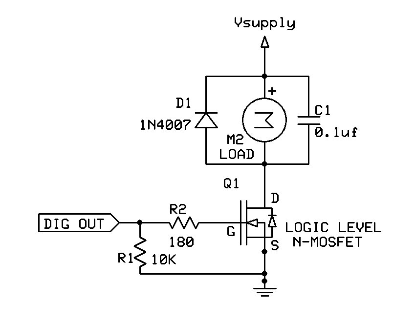
If the LED headlamp is designed for 12V operation, it should be fine for flashing Morse code signals using the MOSFET circuit above, and the RFP30N06LE is a good choice. You don't need the diode and capacitor shown parallel to the load.
Bulbs with filaments burn out quickly when flashed.
On vehicle electrical systems, it is more usual to switch on the high side, because the accessory you are switching may be earthed directly to the chassis somehow. This would mean a P-Channel mosfet.
I ordered a pro mini and has thus far been unsuccessful in programming it. I am using an uno to program it and can successfully send sketches to the uno but not the pro mini. I also found that the way to connect the pro mini to another board to program it is complex enough that it defeats the purpose of going to a smaller board. My requirements are to have a water resistant enclosure that allows access to the arduino to easily reprogram the morse code message and this does not seems practical with the pro mini with how it must be connected even if I got a FTDI and the uno is simple, just plug in the USB.
I have yet to test the headlight Paul__B and I believe to determine whether or not I need a pre-heat circuit is whether the led functions properly or cuts in and out, is this correct? I have heard in some instances that even with a regulator a stator does not produce "clean" enough power for leds.
The motorcycle does not have a battery TomGeorge. It started life as a motocross bike and have upgraded the stator to handle the additional power needs of a headlight and brake light. Companies such as Baja Designs use a similar setup with their dual sport kits which provide everything you need to make a dirt bike street legal.
I orderded a mosfet before you posted 6v6gt, so I am going to try and make the one I ordered work.
How Can I connect the mosfet to the uno and can I remove the pin connectors on the uno to solder the connections? Googling provided answers using breadboards but there must be another way?
One more challenge is how to wire power to the arduino itself, I can run power from the stator after the regulator but how to make the actual connection? Remove the uno power port and solder to that?
gradelb:
I am building a custom motorcycle that is not street legal. It is a show bike
Just me but, in that case, if ultimate compactness is not a deal killer I'd just go with a plain old relay. The contacts aren't polarity sensitive so you can connect to either voltage or ground side of the lights and it can be driven with just a transistor. In the unlikely event the contacts wear out just replace it. I assume the Morse code feature isn't going to be running all the time?
gradelb:
I have yet to test the headlight Paul__B and I believe to determine whether or not I need a pre-heat circuit is whether the led functions properly or cuts in and out, is this correct?
Ah! I was responding to:
hammy:
The bulb won’t last long being flashed .
If it is indeed a LED, it has no problems being made to flash repeatedly, but you do need to cite the actual device for us to check.
The motorcycle does not have a battery TomGeorge. It started life as a motocross bike and have upgraded the stator to handle the additional power needs of a headlight and brake light. Companies such as Baja Designs use a similar setup with their dual sport kits which provide everything you need to make a dirt bike street legal.
The problem you may have is electrical noise from the stator and ignition circuit because you do not have the filtering/smoothing effect of a battery.
Your stator may be generating a PULSED DC rather than a smoothed DC current.
This will not be suitable for your microcontroller application.
If you needed small size and REPROGRAMMABLE facitity you need to go to a NANO, it has the same program specs as the UNO and ProMini , but it has the USB interface like the UNO on board.
Tom...
Next, I got my regulator/rectifier and tested it straight from the stator through the reg/rec to the headlight and got this.
Just as you were saying TomGeorge, I believe the flickering is because of the pulsed power from the stator and the reg/rec isn't a fix for it. So then I need a capacitor, but it occurred to me, if I use a capacitor will that mean the on/off flashes from the arduino will be delayed and the Morse code won't work because the capacitor will keep the light after power is switched off?
is there a way to wire it like if the capacitor is before the arduino and headlight then will it flash Morse code properly?
As a matter of course, the capacitor would need to go in the power supply to the Arduino.
It gets tricky. Depending on what else is powered by the alternator, if you connect a capacitor directly to it, then the other devices will likely discharge the capacitor when the alternator falters anyway; you would need a very big one. And it must be rated higher than the maximum voltage that will be generated.
Also, you need a proper 5 V switchmode "buck" regulator to provide your 5 V for the Arduino from your 12 V supply.
A few pieces of information. If the headlight has a filament it draws at least 10x its operating current, if warm less when first ignited. A standard halogen replacement bulbs are generally 55 watts for most vehicles while HID bulbs run at around 35 watts. Increasing the bulb wattage that you use will increase brightness, however because you can easily blind oncoming traffic, some states have restrictions on the maximum wattage your headlights can be. If it is HID there are electronic circuits and controls, and it has a specific ignition sequence, if violated life will be reduced to almost nothing. Calculate your worse case load then select a MOSFET that is rated to operate at that level or greater. I would suggest you get something like a 10 Watt LED and put it in the lamp housing, everything becomes very easy and extremely bright.This response is to help you get started in solving your problem, not solve it for you.
Good Luck & Have Fun!
Gil
gilshultz:
I would suggest you get something like a 10 Watt LED and put it in the lamp housing, everything becomes very easy and extremely bright.This response is to help you get started in solving your problem, not solve it for you.
Don't suppose you just happened to read reply #5?
gilshultz:
I have ... sourced a LED headlight and brake light so I know there are no sensors and if wired correctly will not pose an issue. I believe I just need to figure out the correct way to wire the UNO to the headlight switch so it works as designed and the rest of the wiring for the bike will not interfere.
The bulb is rated to last 30,000 hours and is more than adequate brightness at 2,500 lumens. Is there a way to predict how this will shorten the life? I am not planning on leaving the light in flashing morse code mode for more than a minute at a time and only using that mode infrequently.
Update: Figuring this out has meant going back to the drawing board for the entire wiring harness, ordering a part, waiting for it to arrive, testing to see if it will work and then taking the next step from there. Have not gotten back to how to power the Arduino yet.