This is more of an electronics question than an arduino specific question, but I think the people here will be able to help me regardless. Plus, I want to incorporate arduino into this once I'm done.
I need help with a circuit I'm building. I created a version of this circuit that seemed to work before, but because of what seemed like bad connection I re-made it and now have a significantly larger issue.
I'm trying to build the Boosted Bidirectional Controlled Current Source in the LT1990's datasheet https://www.analog.com/media/en/technical-documentation/data-sheets/1990fb.pdf here. The issue is that my circuit does not follow the mathematical equation shown under the circuit and the current only seems to change when +V and -V are altered instead of the control voltage or sensitivity resistor. This is how I'm building it.

Here are the labeled and unlabeled versions of the circuit I made using tinkercad. To my knowledge, this should be correct compared to the diagram. If it's not, please let me know because the way I have it could be the problem.
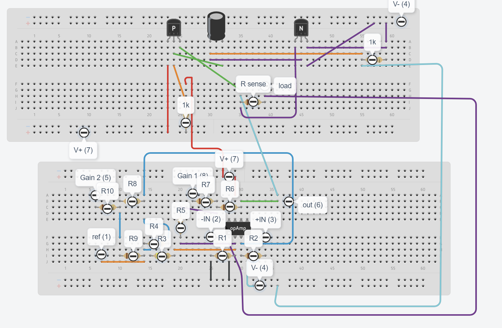
Anyways, I continued to building it on a breadboard like this:

I'm only allowed to post 3 imbeds into this post, so I hipe this photo is good enough.I'm using 2N3904 and 2N3906 transistors.
This is the first problem I'm having, when I have the positive voltage come from the red and the negative from the yellow then the current is negative, which it shouldn't be. I know this can be solved by switching them, but I think that may be part of the problem because I have no idea why that could be the case. Part of why I know something is up with this is because the first time I made this circuit there was no problem having the voltages this way, which makes me think something is wrong with this version specifically.
When I do switch them, the current is not based on the relationship shown in the diagram. Using the resistor I am using (10 ohm) and the voltages I'm using (+2.5v, -2.5v, .1v), the only reason I can think of is that there are resistors in parallel somewhere that are lowering the current.
Please let me know if you have any input, or see something I did wrong, please help me out.
If you need any more information to help, please ask.
Thank you all!

