I have developed a circuit with Arduino Every, DRV8225, 4-20mA to 0-5 V Converter. The Working is just motor rotation according to 4-20 mA input. The box and the motor is attached to a metal flap. and also has ignition sequences for same product.
Having itssue that the motor fluctuates/ hisses at every ignition sequence and misses position.
Its an valve to control air flow. In an Vehicle just like throttle body mechanism. For 4 mA it closes an 20 mA it opens. Beside this circuit there is a ignition transformer for Sprak and Lpg line. The gas combustion happen on spark at full valve open for air. But while spark the stepper motor connected to valve air intake, Fluctuates while sparks happen. At every first start i have homed the valve using a limit sw.
Its a simple circuit.
The control box has ignition transformer, and a 230v to 12v smps and the sequence controller which sense and controls gas and spark.
The body is grounded (earth) while trials
The motor control consists Drv8825 a 100uF cap for motor and 10uf for mA to V converter.
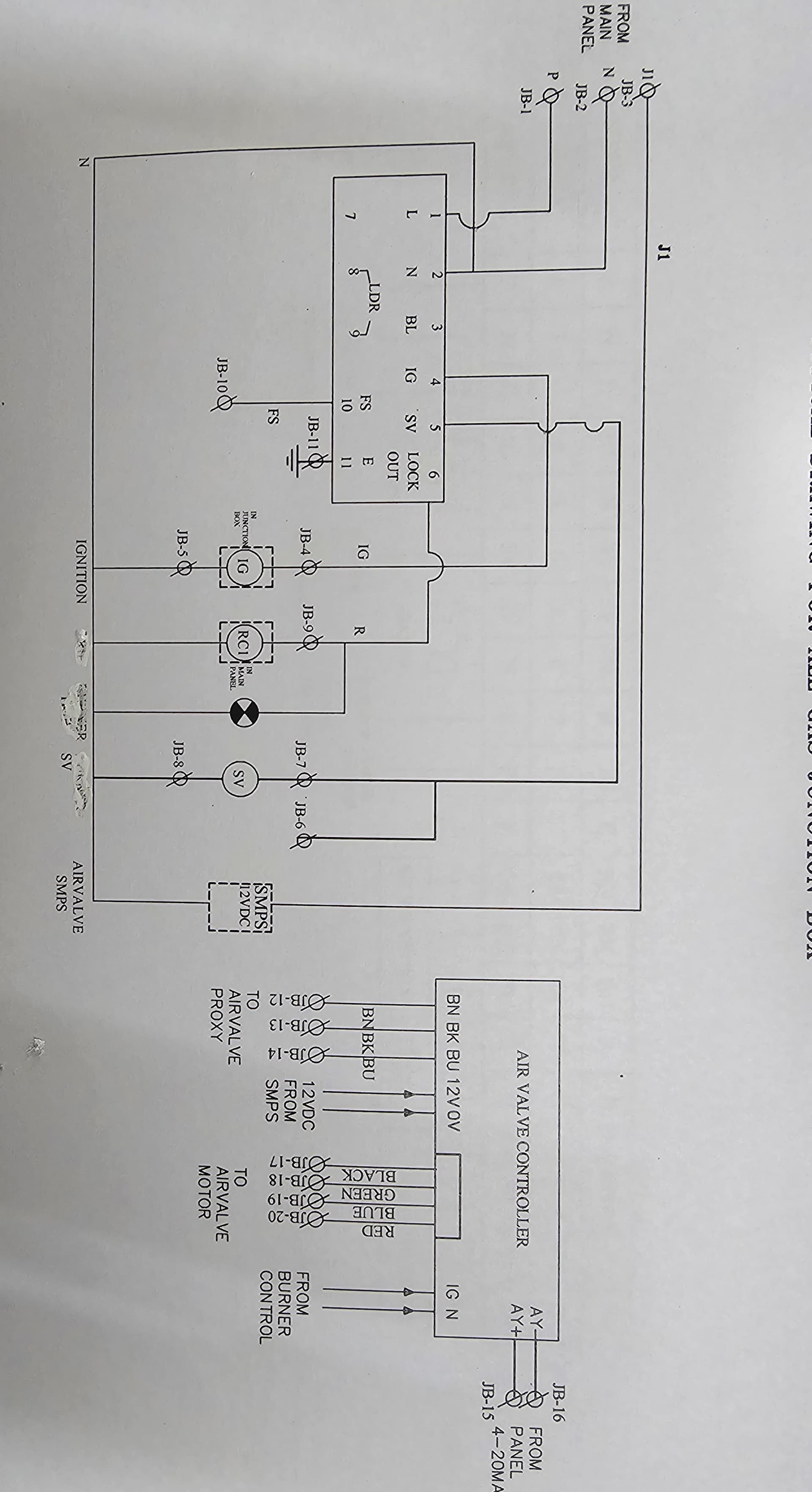
Better to have posted a copy of your circuit, a picture of a hand drawn circuit in jpg, png?
Hand drawn and photographed is perfectly acceptable.
Please include ALL hardware, power supplies, component names and pin labels.
Good schematics
One tiny, aesthetic detail, -12V in J2 would be GND.
You nailed the cause of the interference, sparks are radio transmitters and the circuitry to produce sparks can also be a source of the very same.
One of the users here, @gilshultz have put together a list over documentation from various sources in the industri about automotive electronics, here's a link to the list.
I don't understand "while trials".
Proper grounding is important and in this case two grounds is likely a necessity, with optocouplers to completely separate digital and analog circuits.
"trials" while initial run as a moving vehicle couldnt be grounded.
i need to eliminate the EMI or the frequencies from spark. also tried to seperate the arduino circuit from the ingintion control box. but same happened. the disturbances are maybe from the spark side not the arduino side.
any component or a part can be added?