HELP HELP sim trying to make arduino nano to read signal from esc and send it to led strip so I can see on what throttle position I am for more reference Is a decel light for drift car someone already did it but is to expensive so I need make my
Can you access the PWM (servo) signal before the ESC?
There are lots of tutorials on the internet on how to read the servo PWM signals from a RC receiver.
Hi I’m new on this my friend I have a rc drift car and I whant to add a arduino between esc from rc to reciver and send the signal to led strip
To know if the car is in neutral positions to be one led on green and if I press reverse the led light on red and if I press throttle the led turn on blue I know can be possible someone did it but is to expensive thanks for the help
And depend on the throttle position the led go up led by led

What Аrduino are you using? Have you tried anything? If you expect someone to do everything for you, try paid consulting. I don't mean to discourage you but just because someone has done something doesn't mean anyone can do that thing. This project doesn't seem very complicated to me, but it depends a lot on what electronics and programming knowledge you have.
Im new on this my friend I just know is a arduino nano
I prefer wait for some that want to help me

Here is a demo using arrays. Uses pixels from a WS2812 strip. A pot is used to simulate a servo signal. There are many tutorials on the net about reading the servo signals from RC receivers. Once the signal (duration of servo pulse in us) is read it is mapped to 1 row of a 2D array containing a row (array of bytes) for each desired step. Elements of each row array contains a number that represents the index to the color of that LED ( a long data type holding a RGB value (0x00rrggbb) in the colors array. The length of the strip (in pixels), the number of steps and available colors are easily changed. Tested on real hardware. Use what you will. I used 7 pixels cause I had it laying around.
// by groundFungus aka c.goulding
//

#include <FastLED.h>

#define NUM_LEDS 7
#define NUM_STEPS 7
#define NUM_COLORS 4

const byte dataPin = 9;
const byte potPin = A0;

const long colors[NUM_COLORS] = { 0x00000000, 0x00ff0000, 0x0000ff00, 0x000000ff};
// 0 is Black or pixel off. 1 = red, 2 = green, 3 = blue
const byte rows[NUM_STEPS][NUM_LEDS] =
{
   {1, 1, 0, 0, 0, 0, 0},
   {0, 1, 1, 0, 0, 0, 0},
   {0, 0, 1, 3, 0, 0, 0},
   {0, 0, 0, 3, 3, 0, 0},
   {0, 0, 0, 0, 3, 2, 0},
   {0, 0, 0, 0, 0, 2, 2},
   {0, 0, 0, 0, 0, 0, 2},
};

CRGB leds[NUM_LEDS];

void setup()
{
   Serial.begin(115200);
   Serial.println("starting\n");
   LEDS.addLeds<WS2812, dataPin, GRB>(leds, NUM_LEDS);
   LEDS.setBrightness(60);
   for (int n = 0; n < NUM_LEDS; n++)
   {
      leds[n] = CRGB::Yellow;
   }
}

void loop()
{
   static unsigned long timer = 0;
   unsigned long interval = 20;
   if (millis() - timer >= interval)
   {
      timer = millis();
      // get simulated signal from receiver.  1000us - 2000us
      // map servo signal to choose active row
      int row = map(readPot(), 1000, 2000, 0, NUM_STEPS);

      for (byte n = 0; n < NUM_LEDS; n++)
      {
         leds[n] = colors[rows[row][n]];
      }
      FastLED.show();
   }
}


int readPot()
{
   int servoValue = analogRead(potPin);
   servoValue = map(servoValue, 0, 1023, 1000, 2001);
   //Serial.print("servo value ");
   //Serial.println(servoValue);
   return servoValue;
}

If you have more than a few pixels there will need to be an external supply.
This could easily be done with a tiny85 processor to make it pretty compact.
Dam bro thanks u very much for u help I appreciate I can do it with arduino nano ?
Sure, the Nano uses the same processor as the Uno so there should be no trouble. Use the same pins if you want.
And you are welcome, hope that you can use it.
Easy to program using your Nano as an ICSP programmer. Many many tutorials on the net.
Before you can program the tiny85 you will need to install a core. The core has the files to interface the tin85processor to the Arduino environment.
I do recommend, strongly, the ATTinyCore core.
The linked page has instructions on how to install the core.

This is the esc from rc the one that say reciver are 3 cables one of them is white one is the signal where I connect that on the arduino
I have no experience with reading the RC receiver signals, I have seen many pages that talk about it. I will have to defer to others that have the experience.
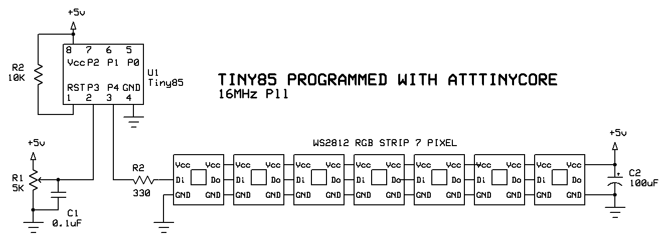
Here is code and schematic for tiny85. Successfully tested on real hardware.
// by groundFungus aka c.goulding
//

#include <FastLED.h>

#define NUM_LEDS 7
#define NUM_STEPS 7
#define NUM_COLORS 4

const byte dataPin = 4;
const byte potPin = A3;

const long colors[NUM_COLORS] = { 0x00000000, 0x00ff0000, 0x0000ff00, 0x000000ff};

const byte rows[NUM_STEPS][NUM_LEDS] =
{
   {1, 1, 0, 0, 0, 0, 0},
   {0, 1, 1, 0, 0, 0, 0},
   {0, 0, 1, 3, 0, 0, 0},
   {0, 0, 0, 3, 3, 0, 0},
   {0, 0, 0, 0, 3, 2, 0},
   {0, 0, 0, 0, 0, 2, 2},
   {0, 0, 0, 0, 0, 0, 2},
};

CRGB leds[NUM_LEDS];

void setup()
{
   Serial.begin(115200);
   Serial.println("starting\n");
   LEDS.addLeds<WS2812, dataPin, GRB>(leds, NUM_LEDS);
   LEDS.setBrightness(60);
   for (int n = 0; n < NUM_LEDS; n++)
   {
      leds[n] = CRGB::Yellow;
   }
}

void loop()
{
   static unsigned long timer = 0;
   unsigned long interval = 20;
   if (millis() - timer >= interval)
   {
      timer = millis();
      // get simulated signal from receiver.  1000us - 2000us
      // map servo signal to choose active row
      int row = map(readPot(), 1000, 2000, 0, NUM_STEPS);

      for (byte n = 0; n < NUM_LEDS; n++)
      {
         leds[n] = colors[rows[row][n]];
      }
      FastLED.show();
   }
}


int readPot()
{
   int servoValue = analogRead(potPin);
   servoValue = map(servoValue, 0, 1023, 1000, 2001);
   //Serial.print("servo value ");
   //Serial.println(servoValue);
   return servoValue;
}
Ok my friend u helps me a lot so what you recommend me to buy apart from the led
What is the output voltage of the receiver. An Nano input can (will) be damaged by any voltage over Vcc + 0.5V so you may need a voltage divider on the receiver output to drop the voltage to a safe level.
Aside from what is on the schematic, I don't know what else.