Help please with Optocoupler Board and Limit Switch

I need to start by saying I do not speak the lingo, I am not an electrical person. So please forgive me and have patience as I attempt to describe my issue.

I have the following four items:
Arduino UNO
12v power supply with ground
12v power supply with no ground
Limit Switch configured for normally closed
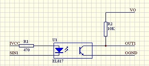
Optocoupler that requires 12v

My issue is attempting to wire the limit switch to the optocoupler board on one side, and to the arduino uno on the other side.

I am not sure if I supply 12v to both sides of optocoupler, one side, or attach ground from optocoupler to arduino ground, and if so which ground?

I have attached a drawing and photos of the items.

Hopefully someone can point me in the right direction.

Thanks
Zach

snap_action_contacts.png

arduino-uno-510x369.jpg

41KJJsGE4fL.jpg

What is the point of some of those pictures ?

Incase I couldn't answer a question using proper terminology I could reference the picture of the component. Also to help understand what I am using, or attempting to use.

I got it figured out. I'll try to create a drawing like the others here have done incase anyone else is in the same situation.

I am not sure if it's the proper way, or if it will resolve my problem with limit switches triggering when they shouldn't.

Are you sure the opto has the correct input resistor for 12V? Can't see the resistor color bands from an end on view, can you post a side view pic?
out.png