I'm trying to create a circuit that will pulse the TSAL6200 IR LED at 600mA with 600us on/off pulses with the 'on' pulses modulated at 38kHz. I've programmed an 8MHz ATtiny85V to generate the correct PWM waveform, verified to be correct on my scope. I'm powering the whole circuit from 3x1.2v AAA batteries supplying a MIC29152BT adjustable low dropout regulator set to 3V.
According to the datasheet the TSAL6200 will have a forward voltage of about 2.2v at 600mA. Given that the BUZ72L drops about 0.1V the series resistor should be (3-2.2-0.1)/0.6=1.16 ohms. The nearest I have to that is 1.5 ohms which would give 466mA.
The problem I'm having seems to be related to the current drawn by the LED circuit. If I wire up the circuit as in the diagram then the ATtiny85V is not happy at all. As soon as my program initiates PWM on pin 6 then the MCU resets itself. If I substitute the 1.5 ohm resistor with a 10 ohm resistor then the circuit will work (trace below), but the current through the LED is obviously nowhere near the level I'm hoping for.
Batteries are not ideal, they have some internal resistance. As soon as you try to draw a large instantaneous current their output voltage sinks quite a bit (V=IR drop through the battery to a first approximation). You're already pretty close to the edge with your regulator: 3x1.2V==3.6V down to 3V, and when your batteries drop out then so will your regulator.
Try putting a large-ish capacitor at the input of the regulator (or at the output, or both). We're talking > 220uF or so. Or you may just want to add an extra battery in series.
You may also want to try slowing down the switching rate of the MOSFET too. There should be some series resistance from the ATtiny to the MOSFET gate, as that gate has a large capacitance (relative to the digital loads the ATtiny expects). I'd put in 100 ohms as that shouldn't slow down the 38 kHz edges much.
One problem is the BUZ72A mosfet you show is NOT a logic level mosfet and will never allow that much current to flow with only 3 volt gate voltage from your processor chip's output pin. In fact I think you will have problems even with most logic level mosfets, trying to pass 600ma at 3 volts with just 3 volt gate drive. You will have to look careful at the graphs from the datasheets of specific logic level mosfets to see if any will work at those conditions.
Your batteries may or may not also be a problem, but for sure you have the wrong switching transistor for the conditions you are using.
One problem is the BUZ72A mosfet you show is NOT a logic level mosfet and will never allow that much current to flow with only 3 volt gate voltage from your processor chip's output pin. In fact I think you will have problems even with most logic level mosfets, trying to pass 600ma at 3 volts with just 3 volt gate drive. You will have to look careful at the graphs from the datasheets of specific logic level mosfets to see if any will work at those conditions.
I think you misread the part number in my post. It's a BUZ72L mosfet. L for [L]ogic. In the datasheet I linked to there is an Id/Vgs chart. It's not easy to read right at the bottom of the curve but I make it roughly 2.5V for Id=600mA.
It isn't clear to me why you need the voltage regulator at all? Especially for the LED?
I want a predictable fixed current through the LED during the life of the batteries so that the range of the emitter is not dependent on the freshness of the batteries.
Batteries are not ideal, they have some internal resistance. As soon as you try to draw a large instantaneous current their output voltage sinks quite a bit (V=IR drop through the battery to a first approximation). You're already pretty close to the edge with your regulator: 3x1.2V==3.6V down to 3V, and when your batteries drop out then so will your regulator.
I may add a 4th cell to give a bit more voltage headroom and also up the size to AA for longer life. I'll do some testing to see if it's worth it. My current problems were not related to the batteries though because I've also tried using a 9V mains supply as input to the regulator and I get into exactly the same reset loop with the ATtiny.
You may also want to try slowing down the switching rate of the MOSFET too. There should be some series resistance from the ATtiny to the MOSFET gate, as that gate has a large capacitance (relative to the digital loads the ATtiny expects). I'd put in 100 ohms as that shouldn't slow down the 38 kHz edges much.
I think you're on to something here. I tried a gate resistor of 100R and it didn't work so I upped it to 150R. That worked. Here's the modified schematic also showing the regulator. The capacitors are not new, they were always there and are sized according to the datasheet. I've also dropped the LED resistor to 1R since Vds on the mosfet seems to be more like 0.2V than the 0.1V I had designed for.
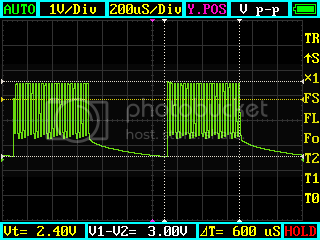
This gives the following 600us pulse shape measured across the LED:
Consulting the LED datasheet I can see that the measured voltage drop of 2.1V equates to a current of about 600mA:
So it looks like I'm now getting the output I was aiming for!
Great, lets hope there isn't any change in temperature. Those curves are done at a fixed temperature, as it change so will the curve. In general putting a 1R current limiting resistor is not a lot of use against temperature variations and if you want to do it properly then a constant current supply will be best.
Slowing down the switch on rate reduces the ground bounce but doesn't tackle the true reason of insufficient decoupling / poor layout.
I think you misread the part number in my post. It's a BUZ72L mosfet. L for [L]ogic. In the datasheet I linked to there is an Id/Vgs chart. It's not easy to read right at the bottom of the curve but I make it roughly 2.5V for Id=600mA.
Your correct, I did misread the device number. It happens.
Great, lets hope there isn't any change in temperature. Those curves are done at a fixed temperature, as it change so will the curve. In general putting a 1R current limiting resistor is not a lot of use against temperature variations and if you want to do it properly then a constant current supply will be best.
The LED datasheet quotes a forward voltage temperature co-efficient of -1.8mV/K. I don't expect to use this device in temperatures greater than 10K more than my test conditions so I should be well within the overall pulse current limit of 1000mA. Yes a constant current source would be an ideal solution...
Slowing down the switch on rate reduces the ground bounce but doesn't tackle the true reason of insufficient decoupling / poor layout.
Are you suggesting an additional decoupling capacitor across the ATtiny? If so what size would you suggest?
I would rather suggest decoupling across the LED, as that's what needs the extra current. You can also prevent some ground bounce (which is what might be causing the reset) by routing the high-current trace around the ATtiny, like this:
--
The Gadget Shield: accelerometer, RGB LED, IR transmit/receive, light sensor, potentiometers, pushbuttons
Are you suggesting an additional decoupling capacitor across the ATtiny?
Decoupling is not just a matter of adding capacitors although they are the main weapon in fighting things. Inductors can also play a part as can better layouts like that described above. http://www.thebox.myzen.co.uk/Tutorial/De-coupling.html