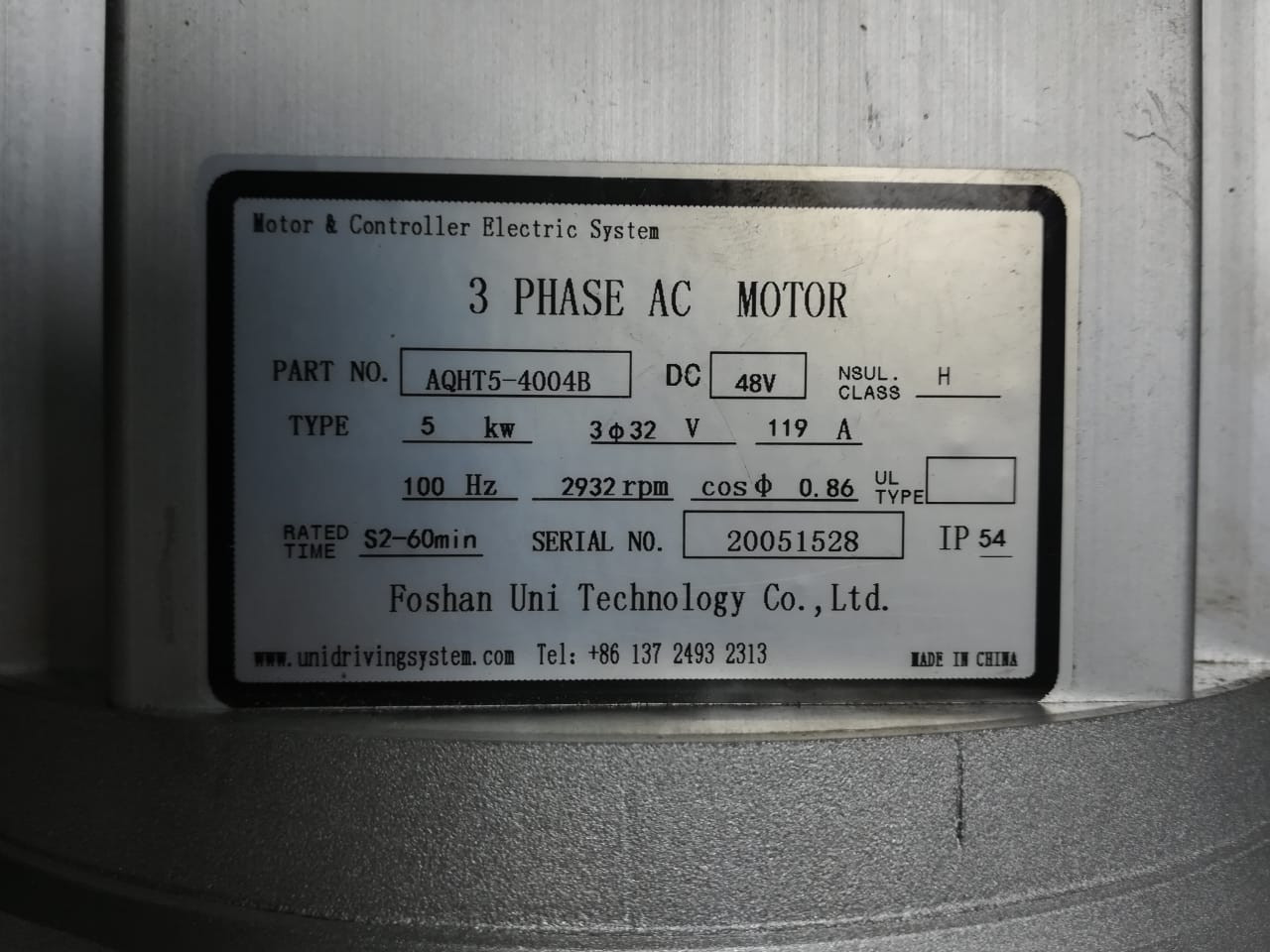
I am looking to design a driver circuit that can run 33v AC induction motor through 48V Battery for Electric Vehicle.The motor tag is attached. I have seen 33v AC induction for the first time.
I was able to design 3 phase half bridge driver on proteus but as proteus does not have induction motor I can not test it. Also, I dont have much experience in power electronics. Can anybody guide me how I can control the speed and direction of this motor using Arduino ?

Your circuit looks interesting however I cannot read it nor determine what parts you used. It appears you use N channel devices for both upper and lower FETs. This causes me to assume the driver chip has a charge pump to drive the gate of the upper FET or a higher voltage supply. I would suggest you spend some time understanding 3 phase circuits and how they work. This link will help you get started. How a Three-Phase Motor Works | Sciencing
1 Like
You might need to learn more about motor control - induction motor control is nearly the hardest sort
to control alas!.
I found these lectures useful, but its quite a high level and assumes familiarity with control theory
to start with: Teaching Old Motors New Tricks - Part 1 - YouTube
The simplest scheme for induction motors is dumb V/f control - this might be a good starting point as
no feedback is needed.
Hi,
Welcome to the forum.
Your circuit/code outputs 3 squarewaves offset and not 3 sinewaves which the motor is designed for.
This will make a big difference to how your circuit will perform and survive?
An inductive load responds and has a load characteristic different in square-wave to sinewave powering.
Have you considered the current that the motor will need to run?
You should be able to model a 3ph motor in proteus, it will be a combination of resistors and inductors basically.
The cosO of 0.86 should help.
Tom... ![]()
PS, The resolution of the circuit diagram is not high enough to read component labels. Did you export the diagram as a jpg or did you screen grab?
TomGeorge:
Hi,
Welcome to the forum.
Your circuit/code outputs 3 squarewaves offset and not 3 sinewaves which the motor is designed for.
All electronic motor control uses square waves for the voltage - the current can be sinusoidal
even with PWM drive as it is smoothed significantly by the winding inductance.
3-phase PWM with sinusoidal variation in duty cycle is a common technique.
Hi
All electronic motor control uses square waves for the voltage - the current can be sinusoidal
even with PWM drive as it is smoothed significantly by the winding inductance.
Yes I am aware that PWM is modulated to produce a current/voltage that is sinusoidal due to the motor impedance, but does the OP know that.
Think a UNO would be pushing to do this job in modulated PWM form.
Tom... ![]()
Hi all! There's here a note about the implementation of a V/f control for an induction motor. You may want to use the attached simulation model to see how it works: V/f control of an induction machine - imperix power electronics
Hope it helps!
Matt
This topic was automatically closed 120 days after the last reply. New replies are no longer allowed.