I need help. I'm working on a simple project to control an ultrasonic mist maker using an Arduino Uno. But for the life of me, I can't make it work. I attached a photo and schematics of my setup and the code.
Relay version: 5V
Quiescent current: 5mA
Maximum current: 50mA
Trigger current: 2-4mA


DC +: then the power supply positive (voltage according to the relay requirements, with 5V; 2, DC-: connected to the power supply negative;
IN1: 1 signal trigger side, you can set the high or low-level control relay pull; 1, NO1: 1 relay normally-open interface; 2, COM1: 1 relay common interface;
NC1: 1 relay normally closed interface
It does not. However, when I use the 12V power supply to power other components they do work. I have four mist makers and all of them does not work when connected directly to the 12V power supply. Am I missing something here?
Here's a link to the mist maker's specs. Can you elaborate more about the transducer and a drive circuit? I'm a newbie when it comes to electronic circuitry.
The part you have is just the transducer. It's the part that vibrates at high frequencies and makes the water turn to mist. However it does not vibrate by itself. It requires some additional circuits (a driver circuit) that will make it vibrate.
Thank you so much for your help. May I ask some more please?
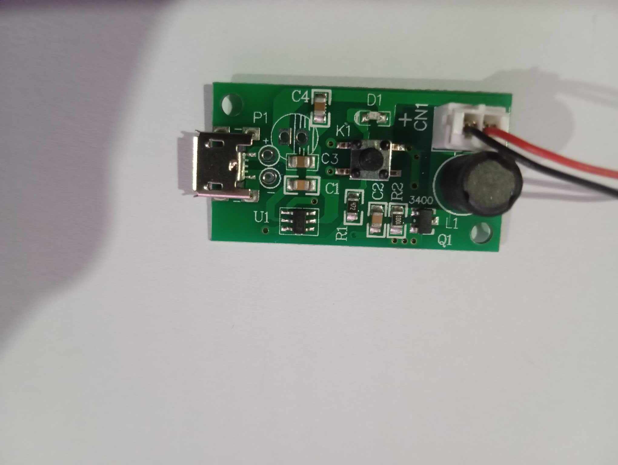
Please refer to the photos. The board is powered using micro-USB which is 5V. However, it has two 'power supply' pins that I can solder to. Can I solder my 12V power supply into it so that it can provide adequate power to the bigger mist maker?
It may not just be a mater of voltage but also frequency. The transducer you have is designed for 1.65MHz, the board you have may be for something different.
I would not connect 12V unless you have instructions for that board that tell you you can.
Actually, the correct driver board will probably generate a voltage much higher than 12V, maybe even as high 40V in order to drive that transducer.
Thank you so much. I've learned a lot. The first being I f-ed up by buying a transducer without a driver board. Now I'm stuck with this and have to figure it out how to make it work.