Help talking to a 74HC165 Shift-in Register

Hi all!

I recently ordered a new PCB design for my project after testing a number of items on my breadboard. One of them was a shift-in register, and although the test was quite brief, I do remember it working without any problems.

My general plan is to add 16 additional inputs to my Teensy 3.5 via a pair of shift-in registers connected to 4off 4 way opto couplers. The circuit I ordered is shown below:

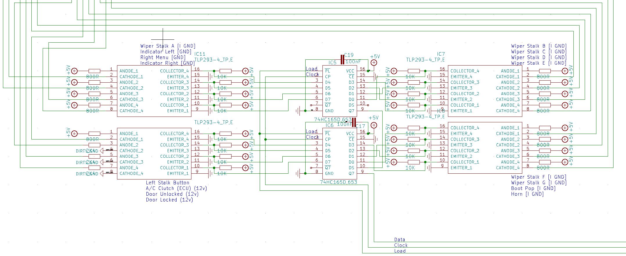
Essentially, each opto-coupler channel is driven by an off-board input, then the Arduino side of the isolator has a 10k resistor connected to 5v and this is connected to the HC165 input channel. The opto-coupler then pulls the pin low to ground when activated.

I included de-coupling caps between VCC and ground very close to each 165 IC then take the inputs back to the Teensy (Data, Clock and Load). For the clock inhibit line, I just grounded this to keep it low permanently so the IC is never inhibited.

When I received the board in the post, I set about testing each function of the board and noticed that I don't seem to be able to get an input from the pair of 165 ICs. Using some very basic test code and the ArduinoShiftIn library, I just get an input of 1111111111111111 every time from pin Q7.

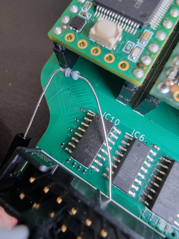
To verify that the code was working, I decided to go back to the breadboard and start from basic principles. I have wired up a single 165 in the same way using the same pins on the Teensy 3.5, but have only connected one of the 165's inputs up to a push button, with the same configuration as the opto isolator arrangement on my circuit diagram. The only difference is that I haven't included a de-coupling cap since I don't have one to hand that can be breadboard mounted (aside from a 22uF cap - I could use this but it may be too big??)

I'm using the following basic code:

#include <ShiftIn.h>

ShiftIn<1> shift;

void setup() {
  Serial.begin(9600);
  // declare pins: pLoadPin, clockEnablePin, dataPin, clockPin
  shift.begin(25, 28, 39, 14); //HC165 Shift In
}

void HC165Inputs() {
  for (int i = 0; i < 8; i++){
    Serial.print( shift.state(i) ); // get state of button i
  }
  Serial.println();
}

void loop() {
  //if (shift.update()) HC165Inputs; //Check shift in register
  delay(1000);
  HC165Inputs();
}

The first issue I had was that using the code with line 19 (if (shift.update()) HC165Inputs;), I got nothing in the Serial monitor, so nothing was triggering the shift.update function. I added the last 2 lines to force printing of the inputs, and what I have is a bit random. These are 1 second apart, and include me pressing the button several times for ~1.5 each - which doesn't appear to have any effect on the printed numbers:

00111001
00000001
00000000
00000000
00000000
00000000
00000000
00000000
00000000
00000000
00000000
00000000
00000000
00000000
00000000
00000000
00000000
00000000
00000000
01000110
11111110
11111111
11111111
11111111
11111111
11111111
11111111
11111111
11111101
00111001
00010001
00000000
00000000

So I'm a little confused now. Before going back to testing the PCB, I'd like to be sure I have some test code that can correctly read on the breadboard, but I don't really understand where I'm going wrong. Any ideas where I can start??

Before you do that look to your opto isolators. What exactly is the type number?

Thing is, opto isolators are not very fast. The ones used for MIDI are about as fast as they get and that works at only 31250 baud.

Try slowing everything down and test them again.

I can’t see any pull up resistors on the outputs of the optos either.

Thanks Mike! I have managed to get the 165 on the breadboard to work now. It seems the inputs were all floating so I've put 10k resistors between all other inputs and ground and now have a stable signal with the button working ok.

To your question, I'm using this opto-isolator: https://www.mouser.co.uk/datasheet/2/408/TLP293_4_datasheet_en_20190520-1916320.pdf

The inputs will just be switches so switching speed is not a priority.

I've got a PC817 on my breadboard and am now trying that on another of the 165 inputs wired the same as the schematic above, though with a 1k resistor on the input LED side. It doesn't seem to work as expected - it does switch the 165 input, but when it does it seems to just be a flicker; it doesn't seem to be able to hold the switched position and it falls back in a fraction of a second.

So looking at the data sheet and adding up all the rise and fall times to the turn on and turn off times shows the fastest possible speed will be a touch under 91KHz.
I somehow got the impression that the clock and data lines for the shift register clocking were going through the optos.

You shouldn't really change the first post except to put code on code tags, as it often makes questions following it look silly. A typical example is to ask for code and the op attaches it to the first post, and is left looking like he did not read the first post.

That could be just bread board wiring, they are notorious for not making good connections. I am assuming you have ceramic decoupling capacitors on all the shift registers.

Hi Mike,

Ok I did some more testing on the breadboard and it seems that it was flickering because the opto led wasn't generating enough current to keep it latched. I was using 5v with a 1k resistor which made just over 5mA. I changed the resistor for a 470R one and it now switches without any problem.

I haven't had time to test the PCB yet but I have checked all connections and it seems to be wired correctly. The datasheet for the 4 way opto I've used quotes a max current of 50mA but not a min. With 800R giving around 6mA, could it simply be that the opto is never switching?

I will test when I get some more time.

EDIT:

Just managed to test the board, and if I use a 470R resistor and connect that between 5v and the opto pin (in parallel to the 800R resistor = 296R equivalent, 16mA), I can see the shift register input change, so I guess it is the same issue and the resistor is too big.

As a temporary fix I suppose I can solder a small resistor in parallel with the existing 800R resistor. How big should I go? Using the 470R small metal film resistor in parallel with the 800R resistor, I noticed the film resistor was getting quite hot under my finger implying that maybe too much current was flowing? What would be a reasonable value to go for for the parallel "fix" (perhaps 1k for a 444R equivalent), and in the new board design to replace the 800R resistor (470R??).

That shouldn't happen, are you sure it is not just your finger getting warm?
What happens if you just use the 470R resister by itself without the parallel 800R?
What wattage is this film resistor, if you don't know then please post a picture of it.

I think the question is small.

The absolute maximum LED current is 50mA but you should never go anywhere close to there.
I would keep the LED current down to 20mA. You can do this with a resistance of 180R, anything bigger will reduce the current.

What is on the cathode side of the opto your circuit doesn't show that.

Hi Mike, Happy New Year to you! Sorry I've been away for 10 days, just getting back into it...

Here's a picture of the PCB with the 470R resistor in shot - it's quite a small one, not sure of the wattage though. You can see the tiny 800R resistor on the board (it's a 0201 case size). I can't cut the 800R resistor out unless I physically cut the trace or pull the SMD resistor off the board.

The cathode size of the opto is just directly to ground, it goes to a wire to board IDC connector where I wire the input to a switch and then to ground, so when the switch is active, it completes the circuit and the opto engages.

To test this, I have simply wired the IDC input pin to a ground pin to simulate the closed switch which keeps the opto cathode permanently grounded. To add the 470R resistor in, I have taken a 5v pin on the IDC, and used a jumper wire to connect it to the resistor, then I touch the other end of the resistor to the opto IC anode pin in front of where the 800R trace comes in, so it gives the effect of two resistors wired in parallel.

To re-wire the circuit, you recommend 20mA and to do this with a 180R resistor - surely this would give a higher current of nearly 28mA according to this online ohms law calculator? Would 250R be better?

The bad news is that the resistor in your circuit is not a 480R resistor, the way I read the colour bands it is a 48R resistor.
The colours I see are -
Yellow, grey, black, gold, brown
Which on a 5 band resistor are
4 8 0 x 0.1 = 48R with the brown giving a tolerance of +/- 1%
Can you please check this with your multi meter to see what value you really have.

I am not sure how you used that online ohms law calculator but I can't see how you came the that conclusion. The formula for resistors in parallel is
1/Rt = 1/R1 + 1/R2

So assume that 470R is in parallel with 800R would give 296R for the total resistance giving a current of
(5-1.25) / 296 = 12.6mA
But you have 47R resistor so this gives you and effective resistance of 45.5R and so a current of 83mA which exceeds the absolute maximum of 50mA for that device.

That is a one eighth Watt resistor or 0.125 Watt but that only tells you the total dissipation which is normally 70ºC above ambient, so it can get hot and it is still OK.
see https://eepower.com/resistor-guide/resistor-fundamentals/power-rating/#

Hi,
Do you have a DMM?
These days with smaller components and manufacturers terrible choice in body colour, so colour code are hard to recognise.
A DMM will help with the final check before putting it in to circuit.

Tom... :grinning: :+1: :coffee: :australia:

Thanks Mike - great spot. I had very quickly checked it on the DMM but hadn't clocked the decimal point position. It is indeed a 47R resistor (I had ordered 470!) This perhaps explains why it was getting hot!

What I meant by my point about the new ohms law calculator was that if I change the board design and replace the 800R resistor with a similar one of 250R value, then I should get 20mA through the opto which would be much better. So my next revision of board design will use 250R instead of 800R. I noticed that I use two PC817X optos elsewhere on the board which also looked a little low on the forward current, so I've increased these by specifying a 1k resistor for the 12v input, and a 300R for the 5v (it likes a slightly lower forward current range than the Toshiba 4 way opto).

Hopefully this will get all of the optos working correctly this time!

Why wait for that. You can remove a surface mount resistor by alternate touching to iron on each side until both are molten then flicking them off with the iron or tweezers. Then get some 247R resistors of the quarter watt type and solder them onto the pads. Or even get some surface mount resistors and replace them. Again a good pair of tweezers will help you.

Hi,
If you solder some 330R SMD on top of the 800R, that will give you 233R.
470R in parallel with 800R will give you 296R.

Tom.... :grinning: :+1: :coffee: :australia:

Thanks guys, both good suggestions. Since I have used 0201 case size, I think probably soldering 330R on top might be easier, though I suppose it's still going to be like performing brain surgery :joy:

I'll give it a go before ordering a new board though, may as well try as you say!

This topic was automatically closed 180 days after the last reply. New replies are no longer allowed.