Hello everyone, thank you for your interest in my article, because my English is quite bad so I use google translate, sorry about that.
I have a small project about measuring power consumption. My design diagram is as shown in the picture, but I am facing a problem: the ESP32 chip is quite hot, and the 9V-5V low-voltage chip of the 5V 500mA power module is so hot that it can burn my hand.
I did some tests and realized that the wifi connection could be the main cause of this problem, in setup() I check the wifi connection, if the connection fails then the ESP32 will open the WebServer and User will enter SSID and WIFI password.
So my question is whether my above thinking is correct, or is there any other reason, I cannot believe that the ESP32 can consume power exceeding 500mA.
Thank you for reading all my shares, hope to receive everyone's help, because the article is quite long so I will share the code in the comment section if you need it to consider my problem.
Thanks for your answer, LarryD!
I'm sorry because i dont have proper schematic rightnow. Based on the picture above, do you have any idea where the heat comes from?
according to the picture you shared, you are having many modules in the syste. try to detach module one by one. like, first remove your power sensor, then remove SD card module. do it step by step and see which attachment is making your voltage regulator hot. if you remove every other than ESP32 board and still power is getting hot then try to change ESP32 module for testing. If you have a digital multimeter then using it in series of power supply (on DC current range) will give you exact idea what is going on there.
Hi @TomGeorge
I tried disconnecting the power one by one and realized that the esp32 is the main cause of the power module heating up. I'm ordering a multimeter so I don't know specifically how much current it consumes to get so hot. I guess I should change the 9V adapter to a 5V adapter to bypass the 9V-5V voltage regulator chip.
Besides, I'm also a newbie so there are many mistakes
Hi, @LarryD.
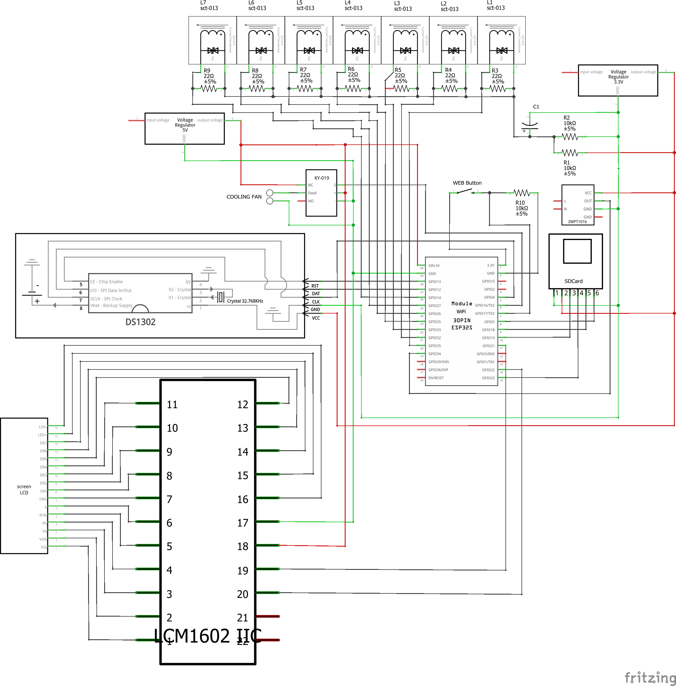
i have a picture of the schematic drawn with fritzing, don't know if it's too messy for you, i just drew it today. Can you see the reason why the esp32 chip heats up? I succeeded in preventing the power module from heating but the esp32 is still hot after 10-20 minutes of operation.
Hot is relative. How hot.
An ESP32 draws about 100mA, so the board dissipates 5volt * 0.1A = 0.5watt.
Most of that (2/3) is the ESP module itself.
So it is normal for the metal part of the board to get warm.
Leo..
If the ESP32 gets hot, an out pin must be under distress.
Measure the current draw on the ESP (5v current to the ESP) while removing output wires to see if the ESP current reduces.
Looks like you might have RX/TX/GPIO21 connected, please review.
Is the 3V3 voltage regulator GND connected to other GNDS ?
Hi @Wawa, thanks for your answer!
I want my project to operate 24/7. In terms of temperature, I don't have a meter right now so I can't say exactly. However, if I compare this temperature with when I checked the wifi connection, it is hotter.
Hi @LarryD, thank you very much for your answer!
About GPIO 33, that was my small mistake when drawing, its task is to read analog signal from SCT-013 L3.
Regarding the second question, I connect the GPIO21(SDA) pin to the SDA pin of the I2C module.
As for the GND pin of the 3.3V voltage regulator, I think not. This is what it looks like after I modified GPIO pin 33 and added red and green, with anode and GND.
However, I have another question, which is that the I2C Module + 16x2 LCD screen are attached together and operate with a voltage of 5V, so do I need to stabilize the 5V voltage down to 3.3V with 2 resistors for the SDA and SCL pins? , and if not then maybe it's because the ESP32 itself is heating it up and I'm just too worried?