Hey all, hope the holidays are treating you well!
I have a unique situation I've been chasing for about a year, but I think I finally have maybe -just- enough info that someone more versed in optocouplers could help me fill in the missing pieces (or maybe I'm still missing too much).
I have been working with a piece of medical equipment that has a separate standalone display screen. The screen runs its own software, and communicates with the main unit using a 4 pin wire. Up until recently I could only say for sure that one was ground, I assumed there was an RS232 RX/TX and an unknown as everything else was RS232 but this didn't seem to be the case.
I want to use a set of ESP32 boards to send this signal via BLE so a wire does not need to be run. I have some code written that can communicate between the boards, but no idea how to interface the boards to the device or screen.
Recently I found a really old wiring diagram from the late 90s, and it shined no light except we're looking at RX.A, RX.K, and TX for the 3 remaining wires.

(I understand there's no ground here but I do have that)
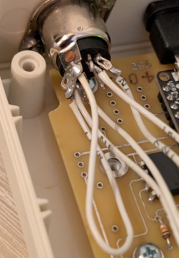
I believed that RXA/RXK were Anode/Cathode, and some sort of optocoupler was needed, but was unsure of the protocol or if I could even interface it with an arduino/esp properly. Until recently, when I came across a device that converted the data to serial input on a computer. I was only able to open it for a second but I was able to take this pic:

The black/white connector can be ignored as it's just an LED that lights up whenever the Metro has power. The connector has 4 wires coming from it, given the pics it looks either Anode or Cathode is not connected, just one RX then TX, 5v, and GND. (GND comes from the shield and is soldered to a dummy pin before going to the board). (Can this work without both Anode and Cathode??)
My understanding is this is a 2 channel optocoupler, likely handling RXA/RXK and sending that data to the arduino, and then using the other channel to handle the TX signal back to the device. My belief is the device sends the screen the data of what it is to display, and the screen responds with a very simple "received" command. (the device will alert if it does not get a response from the chart). It appears they are using A0 and A3 for their TX/RX (not sure on the order but I think it is that order)
I figure this is basically exactly what I am after, but instead of serial data to a PC I just want to BT the data to a matching board which converts it back to the format which the screen will understand.
I am hoping someone may see these pictures, see the few traces they can see, and be able to go "oh yeah this is what is happening". It seems all I would need is an MCT6 and a few resistors for each side of things, as well as a power source for the ESP32 which is easy enough.
Any help would be amazing. If you can determine just this side I can likely come up with the other, but if you are feeling generous this holiday season and want to provide both this side and the matching side's diagram that would be swell.
Thanks!
Edit showing the pin not in use: