Hello,
I have had an Arduino Uno for some time, but just recently found time after graduation to seriously look at it and try to understand it at an intuitive level rather than just powering through as many of the pre-made schematics that came with my booklet to see what it can do.
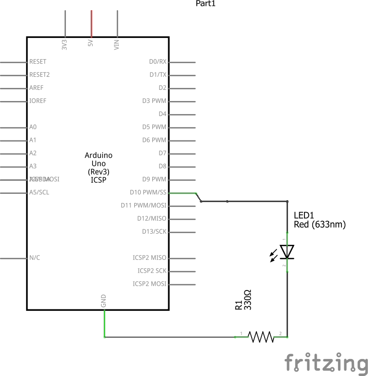
I've taken Electricity and Magnetism as a Physics II course, and so I understand the basic principles behind the forces at play. Maybe I could figure out maths issues once they arise. However, I'm not sure I'm understanding the flow of power in a simple setup wherein a single LED is lit. See the attachment for an example of this (Hopefully I made this image correctly! It does light up in person!).
First I want to say that I think I understand the general concept of a ground (at least from an elementary standpoint) and the complications between the ground on the arduino uno board and an "earth" such as described at here. Additionally, I understand (although I am not at that point yet) that there are complications that may arise when one introduces additional power sources into the equation such as is discussed here.
What I'm really having trouble is understanding a few concepts regarding to the flow of electricity and how the board itself is managing current.
First of all, in the schematic I've included-- I've uploaded an image of the corresponding board as well -- I don't understand the role of the wire from the 5V to the + strip. I note that the LED still blinks if this is removed, and indeed there is nothing connecting the + strip (Now with 5V input I assume) to the components of interest. I know that there is a standard setup that includes this input-to-(+) and GND-to-(-) paradigm. Is it simply to introduce this idea before it is really necessary?
Secondly, I'm not sure how the ground actually DOES its job on this board. Here's what I imagine generally; I'm not an electrician and have no understanding of how electricity works within a housing unit, so I'm sorry if explanations based on that didn't get through to me!
- Power is coming through the USB-B (that chonky printer connection to computer).
- Arduino board recognises this, and uses this to power the 3V and 5V and all the digital pins (although I'm not sure what voltage might be associated with those).
- The power/electrical current from the pins is transferred from the pin to (in this schematic) Row 10.
- Then it accesses the LED anode (+), passes through, lighting up the light when the program says to turn it on/allow the pin to be HIGH.
- The current passes through the resistor.
5a. The resistor is not providing a solid block that only slows current AT that location, but instead slows the flow rather uniformly, which explains why it can be placed before or after the LED in the circuit (the current is the same before the LED and after the resistor, if I remember/read correctly. - The current then passes from the resistor into the - strip.
Here's where I get confused. I know that the current has to go somewhere or it won't move as electrons won't be moving (the conventional flow of current and electron flow discussions set aside). This is why the circuit cannot end there. No flow, no light.
There is the wire allowing the path to travel from the (-) to the GND on the board. However, what happens after this? What allows the current to continue? Where does that current go from there that allows the system to not experience the same issue? I was thinking of two possible answers, but I'm not sure what is correct.
1: The electrical current is somehow sent to a negligible place (sorry for terminology) similarly to what might be there case in a ground literally embedded in the ground (or maybe when connected to a case around the board or something? I don't know what capability the Arduino Uno has to do this, and assuming it's put somewhere, wouldn't that place just "back up" and prevent the flow of current? Or perhaps there's some sort of capacitor or something. I think this whole answer is maybe unlikely?
2: Somehow the electrical current is being sent back into the overall "power circuit" of the board, which is powering the 3V, 5V, digital pins, etc. In which case, the only way for this sort of setup to NOT disrupt the Voltage of those outputs would be to have (at least in the case of the 3V and 5V outputs; I have no idea what the digital pins are doing) the voltage regulators in place AFTER they get their power from the underlying "power circuit" of the Arduino board.
I am ready to move on past lighting up single and multiple LED, etc., but want to fully understand how the overall circuit is actually working. I hope it's obvious that I've been trying to understand and research answers to this, but am missing some knowledge/insight. I keep finding endless information on why common grounds are important for multiple power sources and how the ground is a reference point for the other Voltages in the system.
Thank you, I hope to learn more and truly find out what this device is capable of! I hope this is a suitable location for this elementary question!