I need help proraming a Ardunio for a project. What I need programed is a little program that will control a 8 digit 7 segment display (MAX7219 ) and it will display the current time in 12 hour and it indicate PM with a little led on the first digit lighting up. The time for the clock will be set in code and preferably, easy to change. There is also an LED that needs to turn on when it gets dark, i would like it to be triggered by a LDR, and as well as that when the leds are on i have a litlle potentiometer that needs to conrol the brightness of the LED (When they are on). I have already wired it up to the following pins for the MAX7219 (7 segment 8 digit display) VCC -> 5V, GND -> GND, DIN -> 2(DIGITAL) CS -> 4(ALSO DIGITAL) CLK -> 3(DIGITAL as well). The LED is wired up to the following pins LED positive -> pin 9 (DIGITAL), LED negitive -> GND. The potentiometer is wired up to the following (could not see anymarking but could see a slight A so i will assume thats the input so its wired to A0, the other 2 pins are connected to 3.3V positive. Finally there is the LDR one end is connected to a 10k Ohm resistor that resistor is connected to the 5v positive on the end, and the otherside, that connects to the LDR is also connect to the pin A1, the otherside of the LDR is connected to GND. Thanks for any help, I bought an Ardunio uno R4 minima the other day, so I could do some projects and learn the coding langauge for the Ardunio. Also please ignore any spelling errors, sorry about them, and thank you for any help. Thanks so much, I am very new to Ardunio, and would really like some help. I have also tried to get help from chatgpt but unfortunately the code would not work as planned, no matter how much troubleshooting. I also dont know what catagory to put this so i am putting it in project guide. also just realised that the (Digital) think was not necessary.Thanks again for any help.
If you're looking for someone to write the code for you, try here: Jobs and Paid Consultancy - Arduino Forum
If you're looking to write this yourself, then just start by blinking a single LED on your Arduino and then keep on learning until you've mastered what you need to know.
There should be a current limiting resistor somewhere.
So this is a circuit you did not build yourself? Where does it come from? Do you have a schematic? If not, draw one. Start by posting some clear photos of the setup so people here may be able to help/comment/guide.
No worries, but consider paragraphs instead of a Wall-of-Text (TM) approach. And use a schematic or wiring diagram to illustrate the circuit, not words. Wordy descriptions are time-consuming to read and virtually always turn out to be incomplete, false or at least ambiguous.
As you've found out, it's presently incapable of providing working code for the kind of task you require. Even if it would work (to an extent), it will be poorly structured, poorly documented, difficult to maintain/upgrade and generally highly redundant/inefficient. It's good of you to have tried it, but as you've observed, it's not going to get you anywhere.
1. If possible, collect the following stuff which will help you to learn Arduino Coding and driving MAX7219 Based 8-digital display unit in a friendly way. If you want to continue with UNOR4, that's fine but get the item of Fig-2.
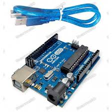
Figure-1: Arduino UNO R3

Figue-2: MAX7219 based 8-digit 7-segment display unit
2. Connect the MAX7219 using SPI Port to avoid bitbanging which is a tricky task.
3. Post codes if you have written any.
4. Provide a link to your LDR.
i have this code but it does not do all that i want it to do: `#include <LedControl.h>
// Pin Definitions
const int DIN_PIN = 2; // Data in pin for MAX7219
const int CS_PIN = 4; // Chip select pin for MAX7219
const int CLK_PIN = 3; // Clock pin for MAX7219
const int analogInPin = A0; // Analog input pin for the potentiometer
const int LDRpin = A1; // Analog input pin for the LDR
const int LedPin = 9; // PWM output pin for the LED
// Create an instance of LedControl
LedControl lc = LedControl(DIN_PIN, CLK_PIN, CS_PIN, 1); // Only one MAX7219
// Variables to store time
int hours = 6;
int minutes = 32;
int seconds = 00;
// Variables to manage levels
int sensorLevel = 0; // Level read from the potentiometer
int outputLevel = 0; // Level output to the PWM (analog out)
int LDRLevel = 0; // Level read from the LDR
unsigned long previousMillis = 0;
const long interval = 1000; // Interval at which to update (1 second)
// Custom segment mapping
byte segmentMap[10] = {
0b01111110, // 0
0b00110000, // 1
0b01101101, // 2
0b01001111, // 3
0b00010111, // 4
0b01011011, // 5
0b01111011, // 6
0b00001110, // 7
0b01111111, // 8
0b01011111 // 9
};
void setup() {
// Initialize serial communications at 9600 bps:
Serial.begin(9600);
// Set the LED pin as output:
pinMode(LedPin, OUTPUT);
// Initialize the MAX7219 display
lc.shutdown(0, false); // Wake up the display
lc.setIntensity(0, 8); // Set initial brightness level (0 is min, 15 is max)
lc.clearDisplay(0); // Clear the display
// Display the initial time
displayTime();
}
void loop() {
// Read the LDR level:
LDRLevel = analogRead(LDRpin);
Serial.print("LDR Level = ");
Serial.println(LDRLevel);
// Control display brightness based on LDR
if (LDRLevel <= 100) {
// Low light, keep display at moderate brightness
lc.setIntensity(0, 8);
Serial.println("Low light, moderate display brightness");
} else {
// Sufficient light, turn off the display
lc.setIntensity(0, 0);
Serial.println("Sufficient light, display off");
}
// Control LED brightness based on potentiometer
sensorLevel = analogRead(analogInPin);
outputLevel = map(sensorLevel, 0, 1023, 0, 255); // Map to PWM range for LED (0-255)
analogWrite(LedPin, outputLevel);
// Print the results to the Serial Monitor
Serial.print("Potentiometer Level = ");
Serial.print(sensorLevel);
Serial.print("\t LED Brightness = ");
Serial.println(outputLevel);
// Check if it's time to update the clock
unsigned long currentMillis = millis();
if (currentMillis - previousMillis >= interval) {
previousMillis = currentMillis;
// Increment the time
incrementTime();

// Display the updated time
displayTime();
}
// Wait 2 milliseconds before the next loop:
delay(2);
}
// Function to increment the time by one second
void incrementTime() {
seconds++;
if (seconds >= 60) {
seconds = 0;
minutes++;
}
if (minutes >= 60) {
minutes = 0;
hours++;
}
if (hours >= 24) {
hours = 0;
}
}
// Function to display time on the MAX7219
void displayTime() {
// Create a string in HH:MM:SS format
char timeString[9];
snprintf(timeString, sizeof(timeString), "%02d:%02d:%02d", hours, minutes, seconds);
// Clear the display before updating
lc.clearDisplay(0);
// Center the time on the display
int startPos = (8 - strlen(timeString)) / 2;
// Display the time string
for (int i = 0; i < 8; i++) {
if (timeString[i] == ':') {
lc.setDigit(0, startPos + i, 0x3A, false); // Display the colon
} else if (timeString[i] >= '0' && timeString[i] <= '9') {
lc.setRow(0, startPos + i, segmentMap[timeString[i] - '0']);
} else {
lc.setRow(0, startPos + i, 0b00000000); // Clear digit
}
}
}
`
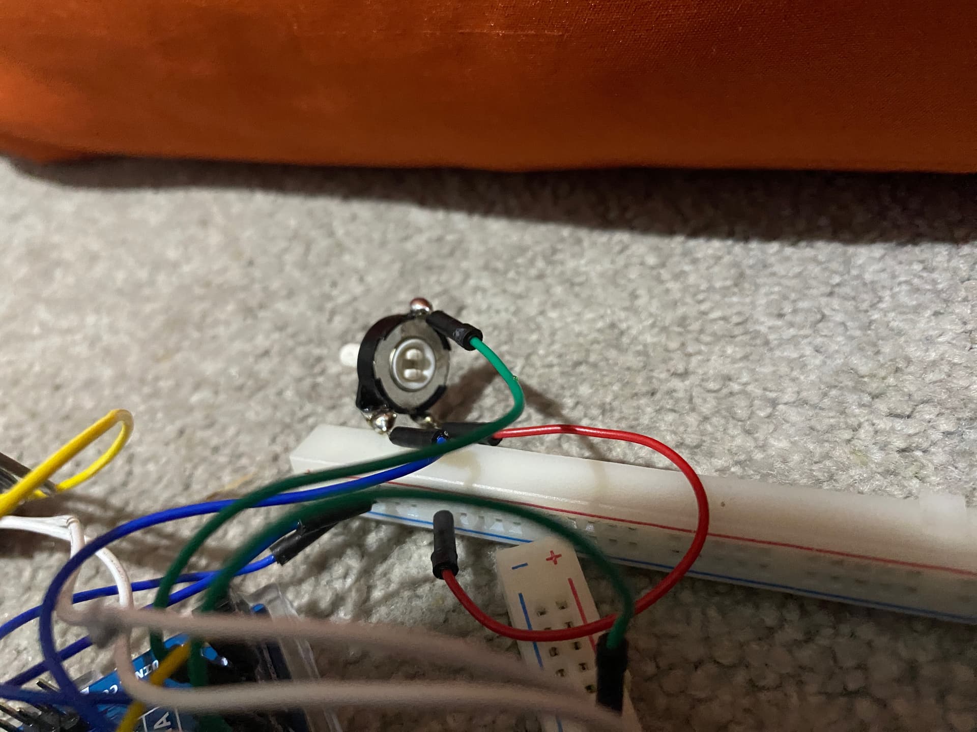
I did wire it up, and i will try make a schematic, but my terrible soldering resulted in melted plastic around about where potenimoter had it's wiring, and it does still does work fine. (Sill learning how to use forum).
Start with the builtin example sketches. We all did.

Which max7219 module are you using? Is the same posted by @GolamMostafa? Maybe there is a more specific library ( for your specific module )? Use it it will make life easier.
This library, for example, seems ( I have not used it ) to support directly that module.
As @sonofcy suggests start with the example included in the library.
Once everythings works as expected make another step: connect the potentiometer and display the value read.
Once everythings works, make another step, vary display intensity...
ADDITION
Sorry, the 'image' you posted is not good, just draw the connection you made,
A rectagle that represent R4 a rectangle that represent the display and the lines that join them 2 -> DI; 4 -> CS ... and so on for pot and ldr
Unreadable, take photos, you look at them before posting to make sure we can see the end of every wire. It may take 4 to 6 pictures.
Throw that pot away. You don't need to solder them, they are designed to fit into the breadboard.
Sort of. If you remove the text boxes on top of the connections, it'll be easier to read.
The LED requires a series resistor to limit current draw.
You're shorting out 5V and GND on the top power bar on the solderless breadboard. I assume you didn't actually connect it this way.
Otherwise it looks like a good start. Can't judge the connections of the display; it depends on the actual display module you've got.
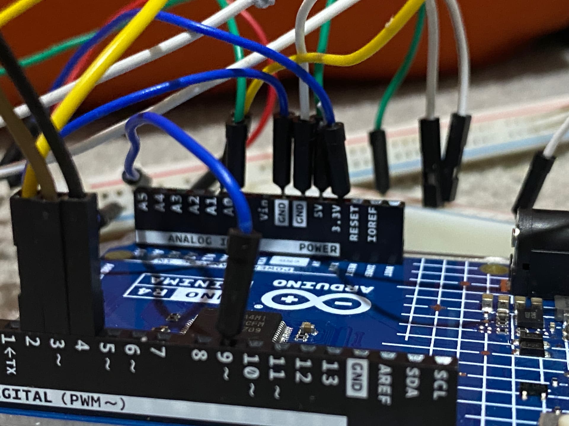
You have said that you have purchased a UNOR4, but you are showing connection using a UNOR3 -- why?
You have said that you have 8-digit MAX7219 driven display unit, but the display unit so shown does not look like that -- why?
Please, show the pictures of your Arduino UNO R4 and the display unit to get help.
Can you please post a copy of your circuit, a picture of a hand drawn circuit in jpg, png?
Hand drawn and photographed is perfectly acceptable.
Please include ALL hardware, power supplies, component names and pin labels.
Sorry but forget about Fritzy, and use proper acceptable symbols.
Tom.. ![]()
![]()
![]()
![]()
Yes, that is the display I am using.
I could not find an ardunio R4 in tinkercad libary, I will send pictures of ardunio when I am able to.
I did in this case because this part was salvaged, I watched a tutorial on led diming and it worked! But i could not put the complete code together and still make it work.
Take a picture of your UNOR4 and post it here.
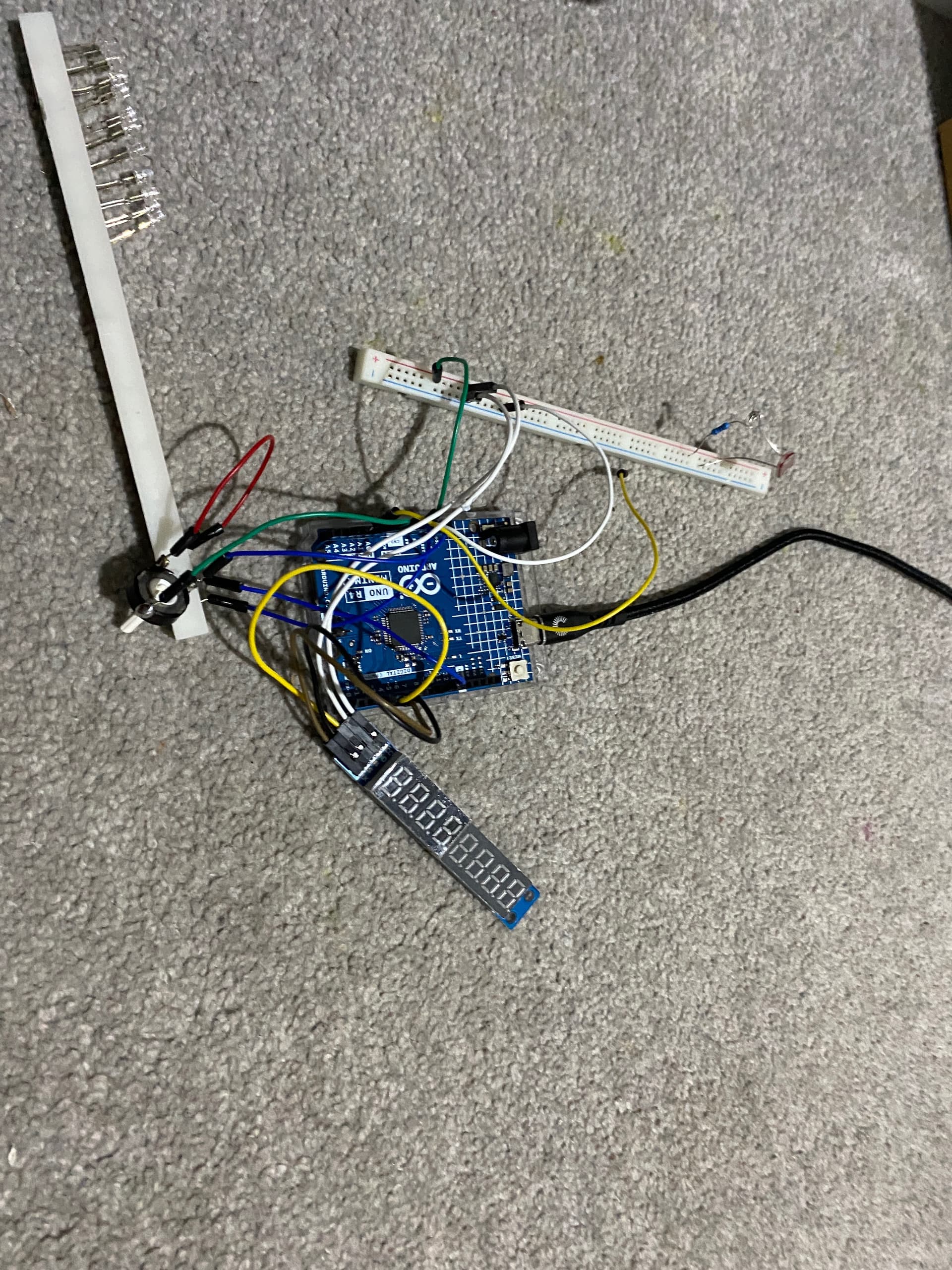
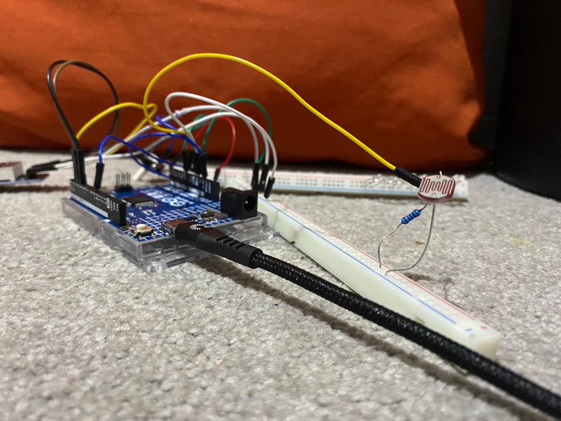
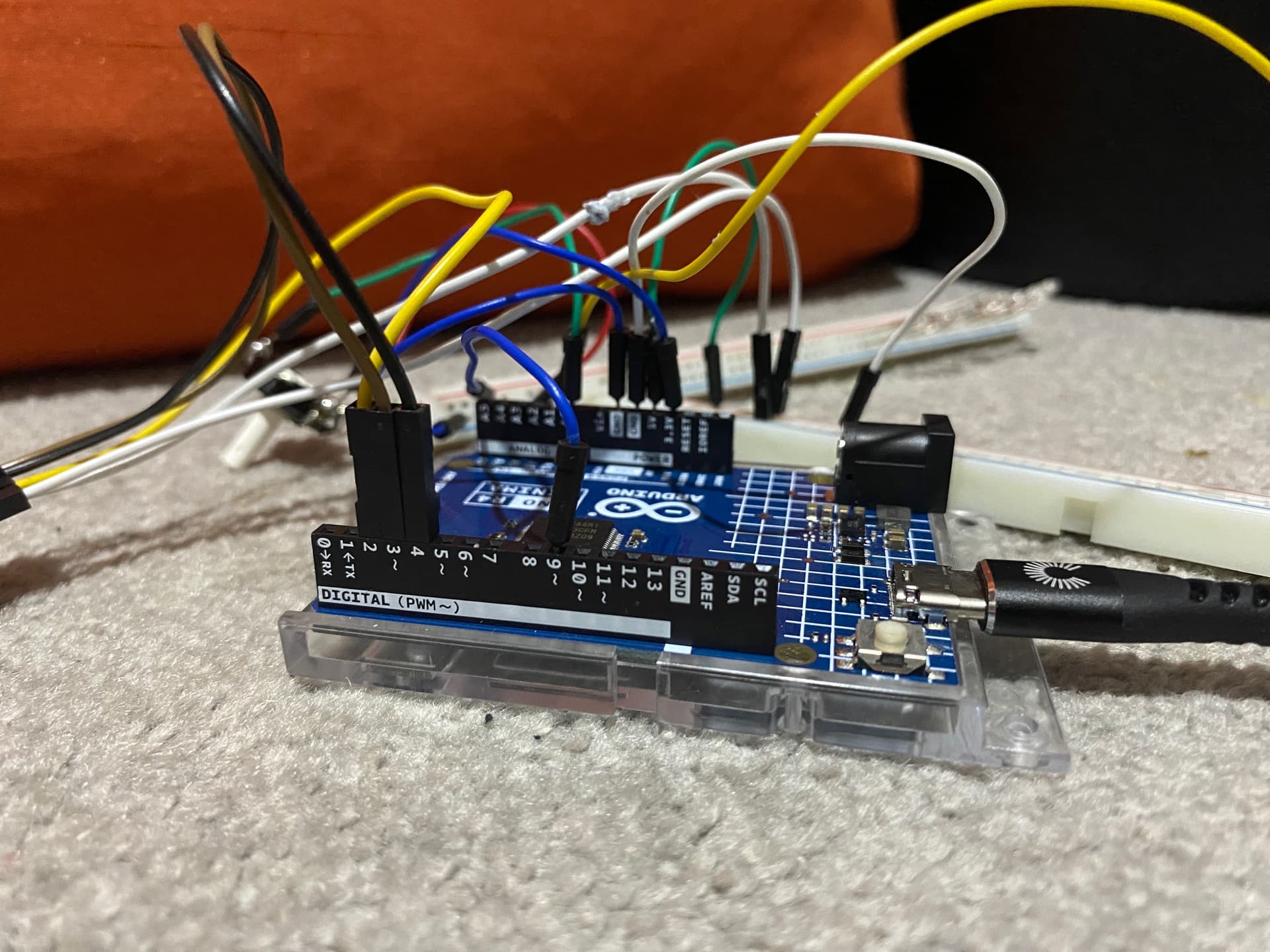
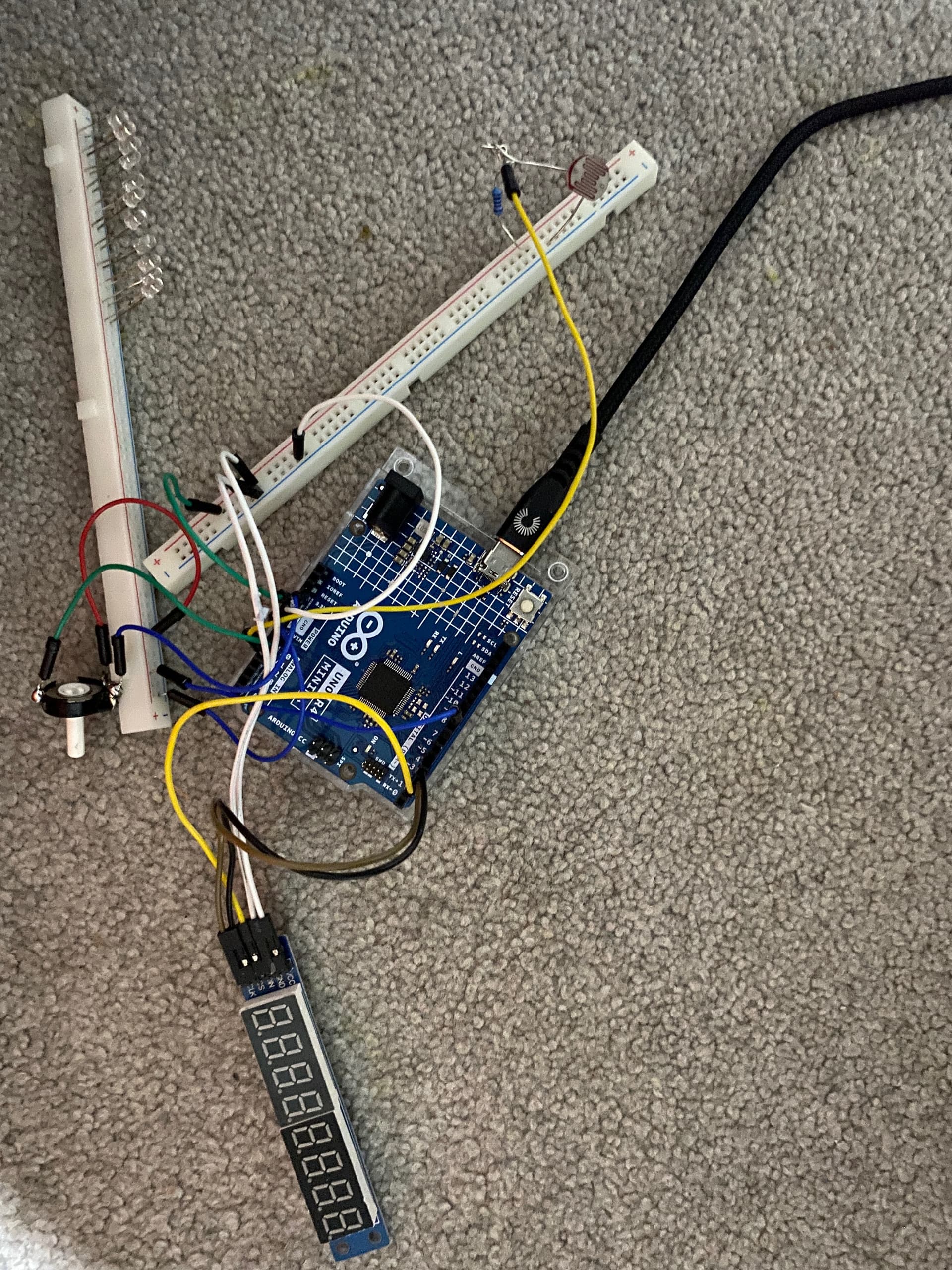
As I said to about 3 people before I will send a picture of my setup and upload to forum, Sorry for any blurryness. I admit the wiring is very messy, but as sugested i took photo's.
(I have 5 pictues but i can only send 3 at a time).