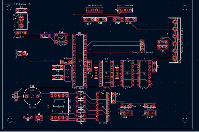
Hello! I am currently creating a project where a part of it contains a timer circuit composed of JK flipflops ICs and an AND IC. the signals generated will be forwarded to the 74LS48 decoder and display the output onto the 7-segment LED display. It should countdown from 7 to 1. The problem is why is the 7-segment LED not changing in value? we verified that the clock is indeed working. Here are our projects along with the schematic diagram and PCB diagram. Any help is appreciated!
I'm a bit confused. Did you already assemble this PCB? Or you expect to see it counting down in KiCAD?
A PCB layout is useless for debugging circuits. Circuits should be prototyped and debugged before you even think about a PCB layout.
The schematic is incomplete. There seem to be connections off the bottom edge of what is visible. Please correct this so we can help.
However, it does show an atmega328, which the schematic does not! With that chip in the circuit, the flip-flops, and-gates and decoder are not needed.
Need to see the complete schematic not just a fragment.
Hi, @cadbery322
Welcome to the forum.
HOW?
Do you have a DMM? Digital MultiMeter?
Can you please tell us your electronics, programming, arduino, hardware experience?
What is you project?
What is it connected too?
What is U1?
https://forum.arduino.cc/t/how-to-get-the-best-out-of-this-forum
Thanks.. Tom.... ![]()
![]()
![]()
![]()
Hi, so this was already tested in the breadboard and everything is working as planned. The schematic diagram was then created based on there and this is then assembled in the PCB, though the seven segment just does not seem to update.
@cadbery322 - what informed your choice to do things in hardware that it does seem would be something the microprocessor could handle in addition to whatever it is doing now?
Just curious.
a7
Still chopped off at the bottom.
What is the part number of the 7 segment dispaly?
The one you show on the PCB does not match the one in the schematic.
What are the values of R3, R4 ...?
In any case the LS48 can only source 1.3mA so it won't drive most 7 segment dispalys.
You need some transistors or a driver IC
star ground!
why are the big capacitors connected with the tiniest traces available? And where is the gnd pour?
Hi, @cadbery322
[soapbox]
You have purchased a blank PCB, loaded with copper.
You are paying someone to remove that copper, which you purchased.
They are not giving you a discount for the copper they reclaim.
You have plenty of room so keep YOUR copper and use it to help provide strong solder points and good current carrying capacity.
[/soapbox]
Do not be afraid to make your tracks wider.
Have you used your DMM to check every trace is a per your schematic?
Tom.... ![]()
![]()
![]()
![]()
Exactly. Using those logic chips doesn't make sense.
The MCU can replace all those ports and drive that display directly.
Maybe OP did run out of pins, not realising analogue pins are also digital pins.
Leo..
Hi,
I see you have the RST pin on your FF's connected to the pin PB4 of your microcontroller, what is the logic state of that pin?
The clock input of your FF's are also connected to the microcontroller, however, you mentioned that the clock is working, right?
I see the BI and RBI pins on the 74LS48 are not connected. The datasheet indicates those pins can be open, however, what happens if you connect them to a stable logic state?
just out of curiosity, you mentioned the circuit should countdown from 7 to 1, but this circuit counts from 7 to 0


