So I had this 3xAA battery powered twigs light (it said low power max 3ma per led on the box if i remember correctly), i decided to connect to mains and add wireless control with the d1 mini, from the idea with the help of grok i made everything, and it worked great for months.
Then suddenly recently I noticed the leds were flickering, I asked grok and did some changes, there was no cap originally (i feel like it made it worse), and the D5 resistor was 1k initially i replaced it with 330R, grok is now repeating the same stuff and I dont know what to do to fix it.
Is anything wrong with the wiring? I need help to diagnose/fix it.
I tried 3 different adapters, and usb cables, still same,
Tried setting 5khz pwm from the default 1khz with analogWriteFreq(5000);, still same
The flickering seems to be worse with more brightness, or its just more noticeable.
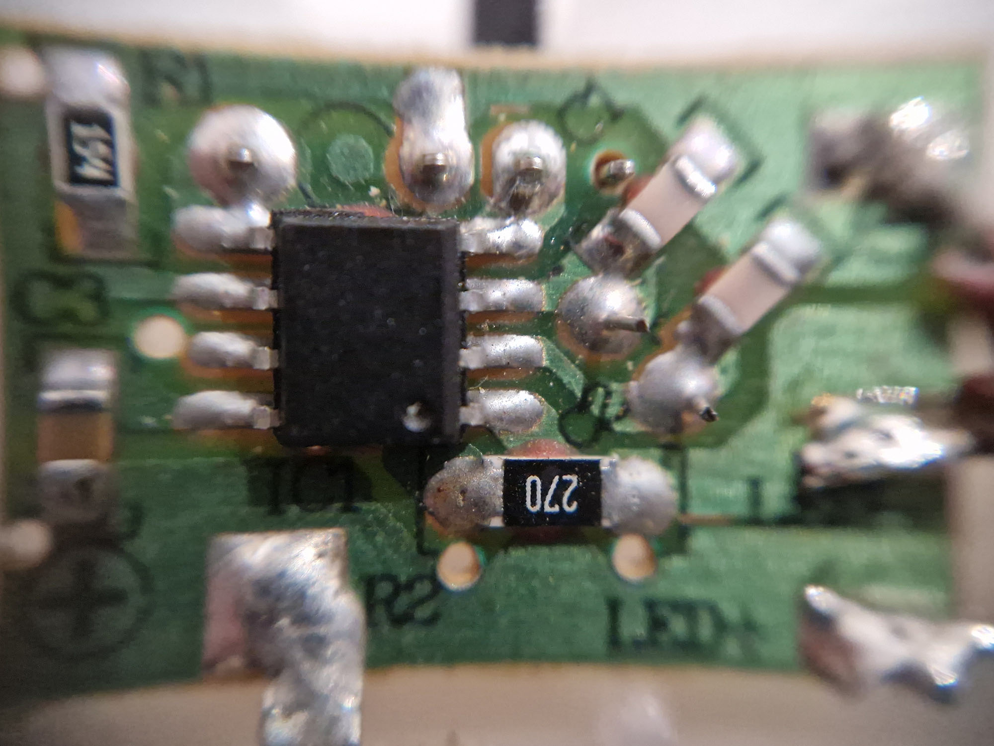
First image is current wiring, second image is the board that was in the original case which was powering it with batteries.
VIdeo: Watch flickering | Streamable
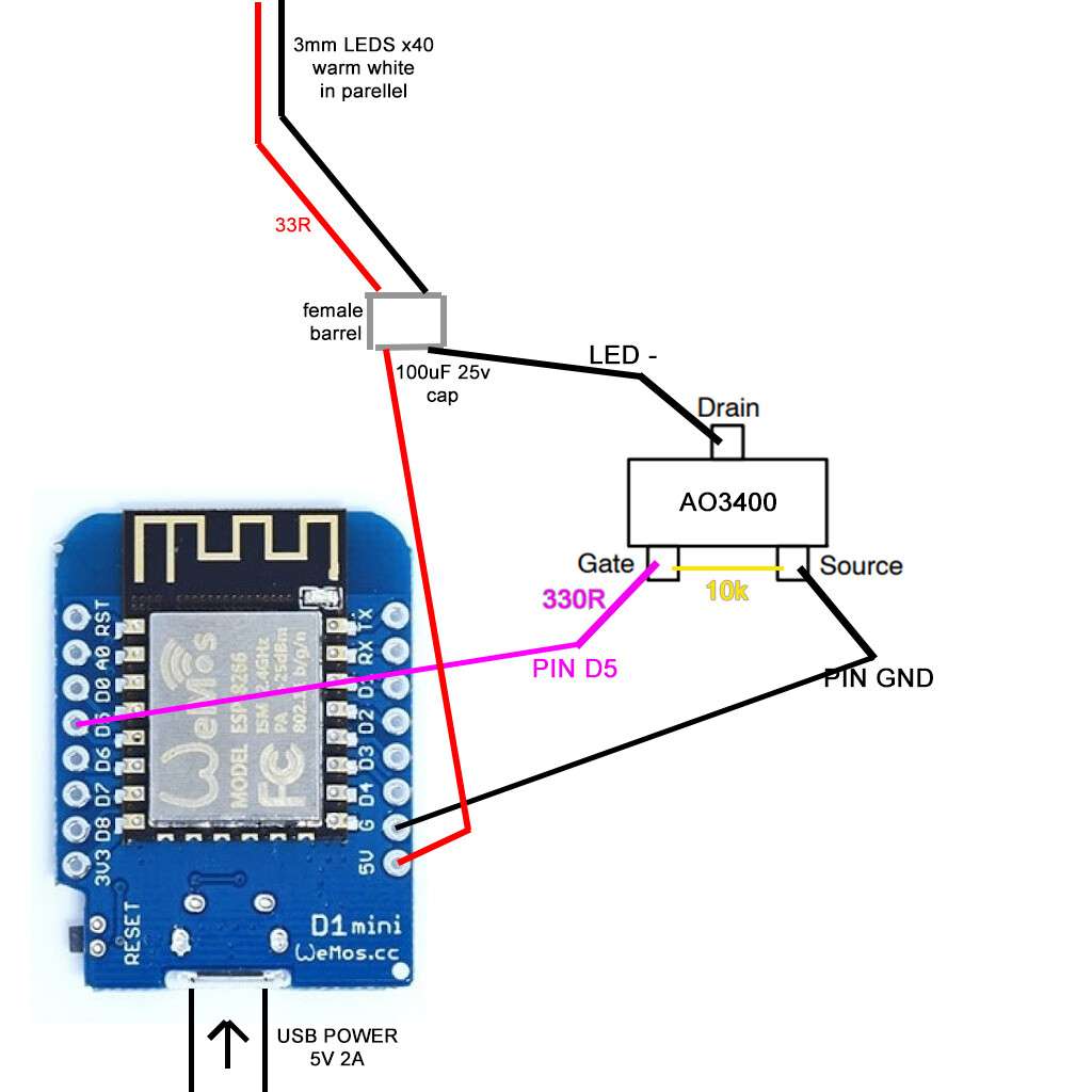
From your picture I expect you may blow the MOSFET if you have not done so already. The cap causes a massive current when switching the MOSFET on and you are far from fully enhancing it. Put the cap between +5 and ground.
Removed the previous cap, and ive put a 470uF 16v rubycon on the 5v and gnd, pretty much the same, might be maybe less erratic but faster flickering, i dont know how it worked fine for months without a cap, im puzzled, i tried a simplest sketch possible to eliminate my code with web server/etc even tho it also just sets the pwm value and its static at that value, same result
void setup() {
  pinMode(D5, OUTPUT);
  analogWrite(D5, 0);
}

void loop() {
  delay(2000);
  analogWrite(D5, 200);
  delay(10000);
  analogWrite(D5, 50);
  delay(8000);
}

How did you decide to use a 33ohm resistor in series with the LED string?
Well I dont think the leds have any resistor, at least that I can see (if its not inside each led casing that has 2 wires in 2 wires out), and I saw that the original pcb had a 27ohm on led- with 4.5v so I thought this is fine for 5v, and grok did some math and didnt disagree 
Actually before this one, I had a 12ohm 0.5W on there when it started flickering then ive put this 33ohm 0.5W
Well that would have more than doubled the current to the LEDs.
Not sure if that would have damaged them.
They run like that not with full brightness but pwn value at 128 from dusk to midnight then at 10 pwm till dawn, so it may be late then for anything with them, damn grok, should have come here for advice
Edit: I have disconnected the led wires and hooked them up to the original battery powered case, they flicker, so this pretty much confirms they are gone, oh well, may replace the leds sometimes in the future with some normal current ones, say 15-20ma, what would be the correct resistor then to use with this wiring to avoid damaging them?
If you do that then you need a separate resistor for each LED. The value of the resistor will depend on the Forward Voltage (Vf) of the LED, you find that in the datasheet.
For a White LEDs the Vf is around 3V.
Your supply voltage is 5V.
Select the LED current to give you the desired brightness but should not exceed the maximum stated in the datasheet( usually 20mA).
Here is a calculator and explanation
https://www.allaboutcircuits.com/tools/led-resistor-calculator/ation
However note that if you set the current to 10mA then the total current for 40 LEDs will be 40 x 0.01 = 400mA.